Two-stage gas washing method

a gas washing and two-stage technology, applied in the field of hydrocarbon production, can solve the problems of consuming a lot of energy, unable to readily apply the gasification strategies known from coal, and still harmful levels for further chemical processing, and achieve the effect of reducing energy consumption

Active Publication Date: 2012-08-23
NESTE OIL OY
View PDF3 Cites 13 Cited by
  • Summary
  • Abstract
  • Description
  • Claims
  • Application Information

AI Technical Summary

Benefits of technology

[0012]This method and embodiments thereof provide advantages. One advantage is a process design, wherein the need for thermal conditioning and heat exchanger equipment, especially for cooling, is significantly reduced compared to processes using methanol wash only. The two-step washing arrangement is necessary because of high levels of both H2S and CO2, but surprisingly the H2S removal in the first absorption step effects the second absorption by releasing the requiremen

Problems solved by technology

These impurity levels are still harmful for further chemical processing and the gas must be purified.
The strategies known from coal gasifica

Method used


Image

  • Two-stage gas washing method
  • Two-stage gas washing method
  • Two-stage gas washing method

Examples


example 1

1 Example 1

Semibatch Absorption Tests of H2S Removal, Using Aqueous Copper Sulfate (CuSO4) as a Model Absorbent of the First Absorbent Solution

1.1 Materials and Methods

[0118]The absorption experiments were carried out using a micro reactor equipment for WGS reaction. Semibatch absorption tests of H2S removal, using aqueous copper sulfate (CuSO4)-solution as absorbent, were carried out in a simple 0.5 liter gas-wash bottle with magnetic stirring, placed in the product line of a micro reactor before the online mass spectrometer.

[0119]Absorption tests were carried out at room temperature and atmospheric pressure. Total gas feed flow was 12 dm3 / h to the WGS reactor. The basic gas feed composition is shown in Table 1.

TABLE 1Basic feed composition.Total flowH2OCOCO2H2N2CH4litre(NTP) / hvol-%vol-%vol-%vol-%vol-%vol-%12.03612222451

[0120]The impurity components were purchased from AGA as dilute hydrogen mixture gases H2S / H2, COS / H2 and NH3 / H2. In the feed, H2S concentration was 500 ppm (vol) i...

example 2

2 Example 2

Absorption Test for H2S Removal from Syngas in Packed Bed Absorption Column

[0139]Absorption tests for H2S removal from syngas in packed bed absorption column were carried out in a Pilot scale test unit. The absorber performance was tested in a syngas preparation plant in Varkaus, Finland.

[0140]Absorber details and data sheets are shown below:

Absorber: packed bed absorber, packing metal, 2-in or 50 mm, surface area 100 m2 / m3,[0141]height: 9 m, diameter 0.1 m.

Feed Gas: feed rate: 50-60 kg / h[0142]pressure 30 bar, temperature 25° C.[0143]Composition / mol-%: CO 21, CO2 30, H2 31, CH4 3, N2 15, H2S 140 ppm, naphthalene 100 ppm, benzene 1200 ppm and traces NH3 and COS.

Absorbent Feed:

[0144]CuSO4—water, concentration 0.15 wt-%[0145]Feed rate was varied, equivalent Cu2+ molar feed ratio to H2S 1.5-6

[0146]The mol-% of H2S in effluent gas was measured by on-line hydrogen sulphide gas analyser. The measured H2S mole fraction in effluent syngas was at minimum 70 ppb at equivalent Cu2+ m...

example 3

3 Example 3

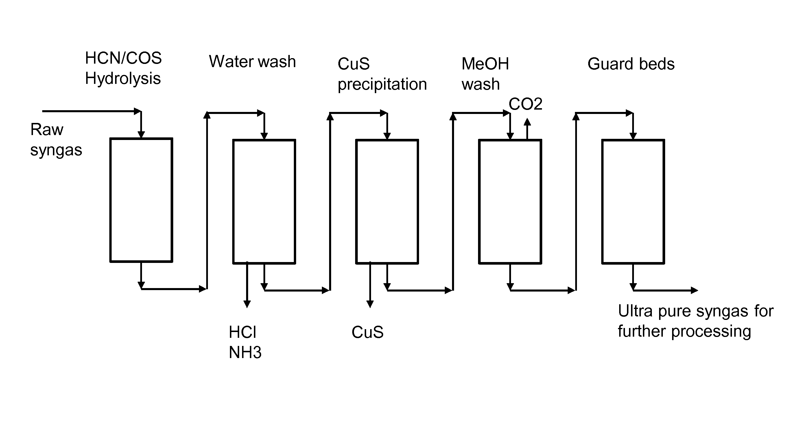
Two-Stage Washing Protocol in Pilot-Scale

3.1 Experiment Equipment

[0148]Absorption experiments were conducted as batches in a pilot scale apparatus. The feed was provided from a syngas preparation plant in Varkaus, Finland. A packed bed absorption column was employed for the wash with aqueous solution, thus the first phase.

[0149]Results were measured with standard analysators; CH4, CO and CO2 with gas chromatography; H2 with FID and sulfur contents with Hobre Novasulf HG400 analysator.

3.2 Materials

[0150]The feed gas, gas to be purified, was originated from gasification of biomass. Therefore there were some minor fluctuations in the feed composition. Composition of the feed gas is compiled in table 5.

TABLE 5Feed gas composition.CO / CO2 / H2 / CH4 / N2H2S / vol-%vol-%vol-%vol-%vol-%ppmFeed gas30283435150-190

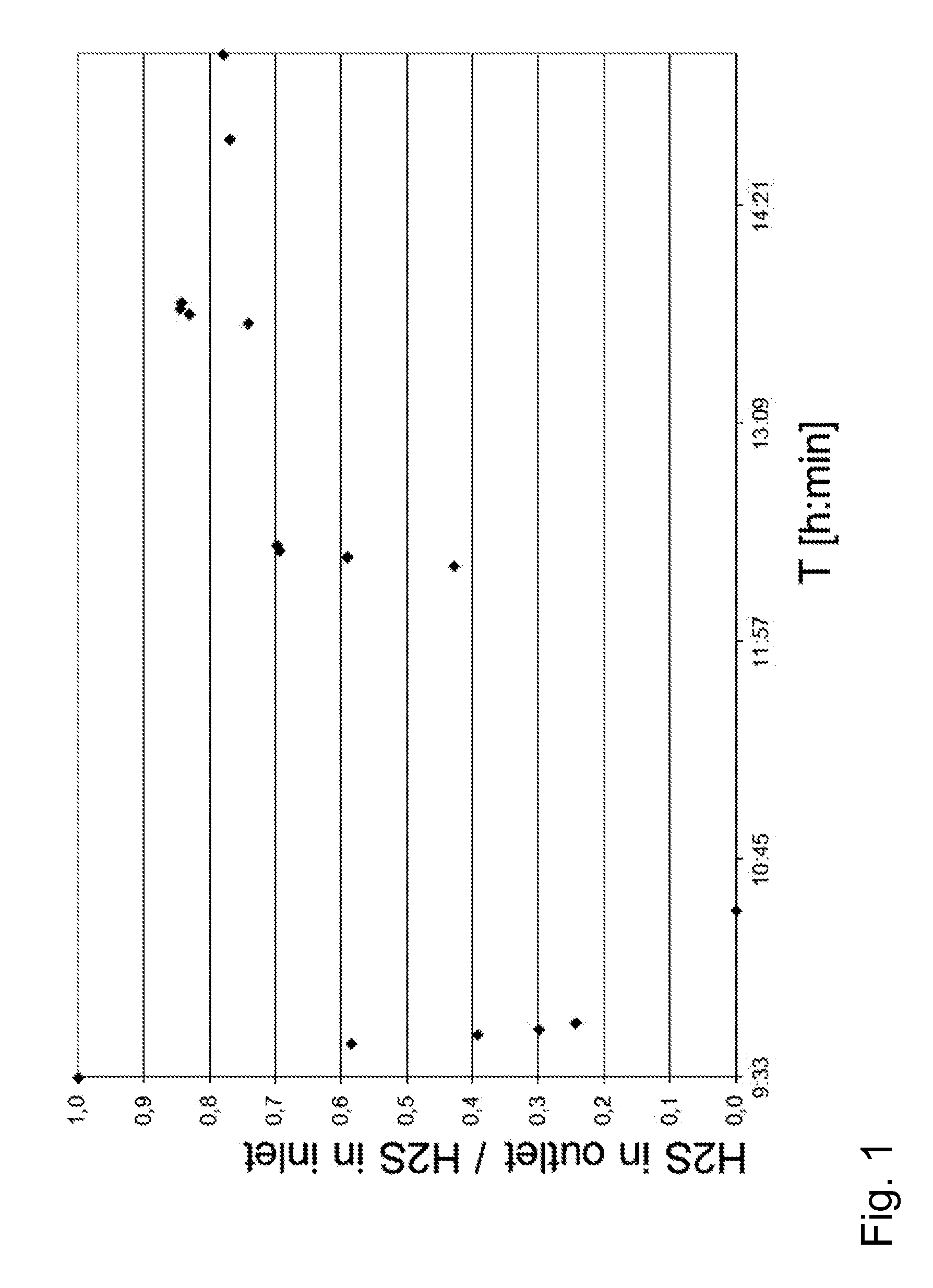
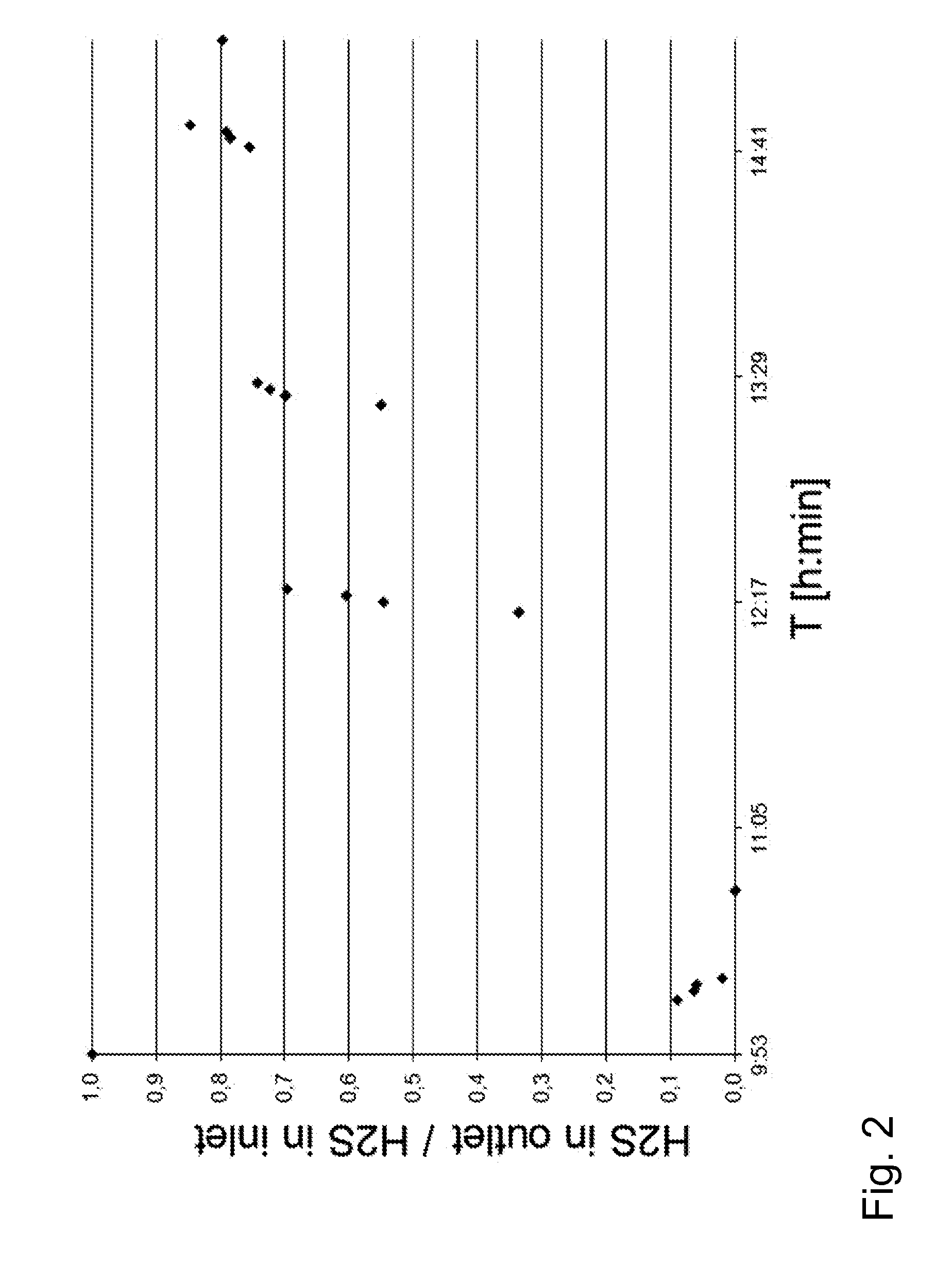
3.3 Conduct of the Experiments

[0151]Total gas feed was 50 kg / h.

[0152]At the beginning of the first absorption step, the CuSO4 feed was zero. As the experiment started, aqueous sol...


PUM

PropertyMeasurementUnit
Temperatureaaaaaaaaaa

Abstract

The present description is related to the field of hydrocarbon production by gasification of carbonaceous material. It provides a two-stage gas washing method as a part of gas refining. More specifically it discloses a method for hydrogen sulfide and carbon dioxide removal from synthesis gas produced by gasification. It introduces a use of a novel combination of wash approaches for this application. As a specific application, this process is utilized as a part of biomass to liquid (BTL) process.

Description

TECHNICAL FIELD[0001]The present description is related to the field of hydrocarbon production by gasification of carbonaceous material. It provides a two-stage gas washing method as a part of syngas refining process. More specifically it discloses a method for hydrogen sulfide and carbon dioxide removal from synthesis gas produced by gasification. It introduces a use of a novel combination of wash approaches for this application, one of which involves a chemical reaction and the other is based on physical absorption. As a specific application, this process is utilized as a part of biomass to liquid (BTL) process.BACKGROUND[0002]The gasification of carbonaceous material produces primarily carbon monoxide and hydrogen, mixture known as syngas. Carbon dioxide, water and various hydrocarbons are abundant side products in the gasification product. Depending on the source and composition of the carbonaceous raw material and gasification conditions, the levels of side products and derivat...

Claims


Application Information

Patent Timeline
IPC IPC(8): C07C1/04C01B3/52
CPCB01D53/1406C10J2300/0916B01D53/526B01D2252/2021B01D2257/304B01D2257/504C01B17/20C01G3/06C10K1/108Y02C10/06Y02E20/18Y02E50/32C10G2300/1011C10G2300/207C10G2300/44C10J3/00C10K1/004C10K1/005C10K1/085C10K1/165B01D53/1462Y02E50/30Y02P10/146Y02P20/145Y02P20/151Y02P30/20Y02C20/40
Inventor WAHLSTROM, JANAITTAMAA, JUHANIEILOS, ISTO
Owner NESTE OIL OY
Why Eureka
Try Eureka