Porous materials coated with calcium phosphate and methods of fabrication thereof

a technology of calcium phosphate and porous materials, applied in the field of methods of coating medical implants, can solve the problems of limited clinical effectiveness and use, early coating methods, electrophoresis methods,

Inactive Publication Date: 2012-10-25
TISSUE REGENERATION THERAPEUTICS
View PDF4 Cites 25 Cited by
  • Summary
  • Abstract
  • Description
  • Claims
  • Application Information

AI Technical Summary

Benefits of technology

[0015]The present invention provides a simple method for coating the internal surface of a porous material, such as a medical implant, with a layer of calcium phosphate. A porous material is submerged or contacted with an aqueous solution that contains calcium ions, phosphate ions, and carbonate ions. The pH of the solution is allowed to gradually rise, during which time the solution is agitated, thereby enabling the formation of a calcium phosphate layer internally within the porous material.
[0017]The step of agitating the solution is provided for increasing a rate of change of the pH of the solution by increasing a rate of extraction of carbon dioxide gas from the solution to an atmosphere above the solution, and the rate of change of pH of the solution is preferably selected by controlling the step of agitating of the solution.

Problems solved by technology

Early coating methods suffered from a number of drawbacks that have limited their clinical effectiveness and use.
For example, the electrophoresis method, while providing a low-temperature process, suffers from low bond strength and typically requires an additional post-process sintering step.
While the plasma spray method provides a coating with a high bond strength, the high temperatures required for the process results in the decomposition of the coating and limit the number of substrates that may be used (e.g. plasma spraying is incompatible with most polymer substrates).
Furthermore, line-of-sight processes such as the plasma spray process suffer from very poor infiltration of porous materials.
Unfortunately, such methods often required incubation periods exceeding three to four weeks for the formation of a suitable layer of calcium phosphate on a substrate, with frequent changes of the coating solution.
Such advancements clearly improve over previous 1×, 1.5× and 2.×SBF biomimetic coating methods by providing new methods that require less incubation time and less coating solution, but still suffer from the disadvantage of requiring an extra gas supply.
However, the process as taught requires the control of the partial pressure of carbon dioxide in the atmosphere above the liquid, which increases the complexity of the process.
Furthermore, depending on the selected ionic concentration and the coating rate, the coating may not be evenly distributed along the substrate surface.
The inability of such prior art methods to internally coat porous structures is particularly evident in Li (U.S. Pat. No. 6,659,489), which suggests that the method disclosed is only adapted to shallow porous structures.
However, porous undercut structures and recessed surfaces are locally porous, with porosity that does not extend deep into the implant or device.

Method used


Image

  • Porous materials coated with calcium phosphate and methods of fabrication thereof
  • Porous materials coated with calcium phosphate and methods of fabrication thereof
  • Porous materials coated with calcium phosphate and methods of fabrication thereof

Examples


example 1

Preparation of Solution

[0098]Under stirring, chemicals were dissolved in 1 liter ddH2O the order as listed in Table 1 to provide a calcifying solution. Each chemical was added in sequence after the previous chemical had completely dissolved. While the sequence below is preferred, those skilled in the art will appreciate that the order of the first three chemicals may be varied.

TABLE 1Preferred Concentrations for Calcifying SolutionOrderChemicalConcentration Range (mM)1NaCl200.0-740.02CaCl2•2H2O 7-143HCl 5.0-15.04Na2HPO43.0-6.05NaHCO3 4.0-20.0

[0099]The prepared solution preferably has a pH value ranging from 6.2 to 6.8 and should be used for coating within 30 minutes of the addition of NaHCO3 (due to the rapid release of CO2 following the addition of NaHCO3). If preferred, the solution may be initially prepared without adding NaHCO3 and could be kept at room temperature prior to adding NaHCO3.

example 2

Method of Coating Scaffold

[0100]PLGA / CaP composite macroporous materials were fabricated according to the method disclosed in U.S. Pat. No. 7,022,522 (Example 10), which is incorporated herein by reference in its entirety.

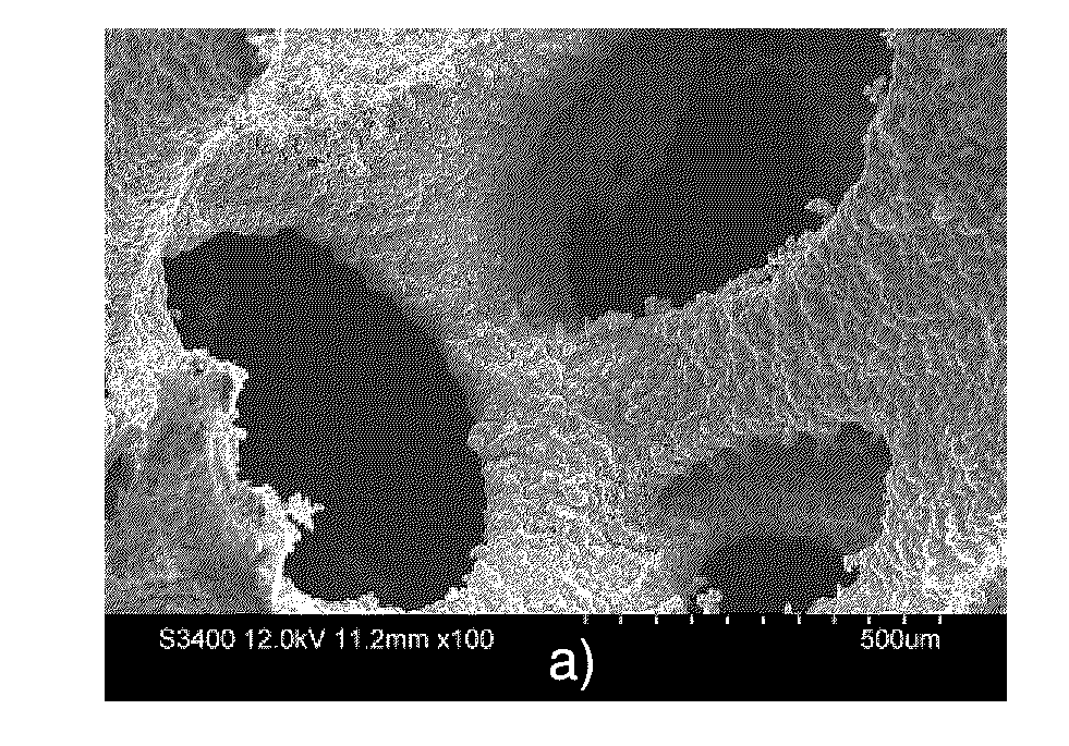
[0101]1.0 g of scaffold cylinders were weighed and put into a plastic mesh bag. Depending on the coating thickness required, 300-600 ml calcifying solution was measured into a 1 L beaker with a stirrer. The mesh bag was completely immersed in the solution and immobilized. The beaker was sealed by an aluminum foil and two small holes with 1.6 mm diameter were created by a 16 G needle. The beaker was then placed in a 37° C. water bath, where the material was incubated under constant stirring at a rate of 200-400 revolutions per minute.

[0102]The bath temperature and stirring rate were maintained over one day. The coated scaffold was removed from the mesh bag and rinsed 3 times by ddH2O before being subsequently dried.

[0103]It was found that the coating thickness could...

example 3

Characterization of Coating by X-Ray Diffraction (XRD) Analysis

[0104]The calcifying solution was kept at 37° C. under stirring for 24 hours, in the absence of a scaffold or other substrate material. The resultant precipitate was filtered, rinsed by ddH2O and subsequently dried.

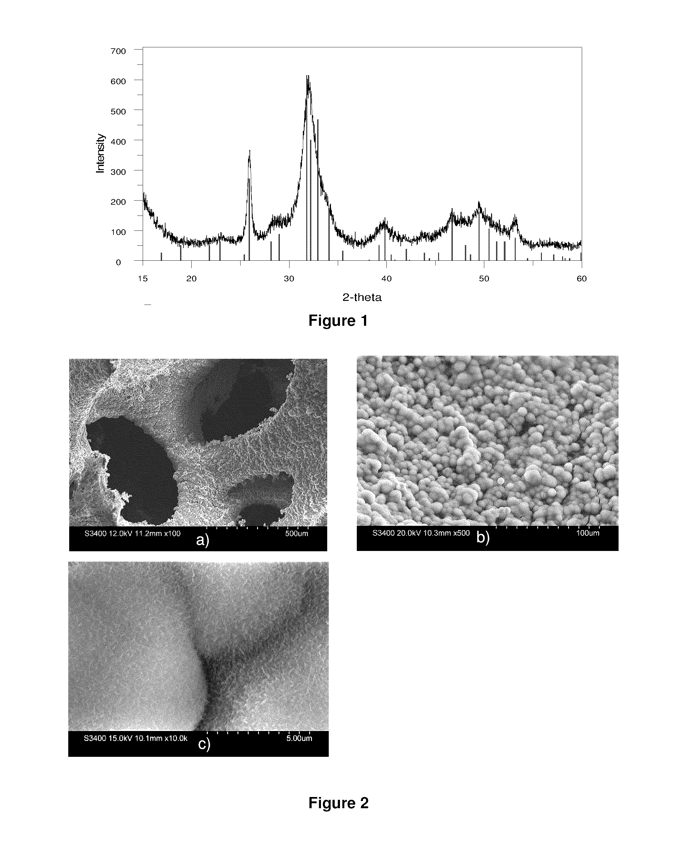
[0105]The produced white powder was collected and XRD analysis was conducted as shown in FIG. 1. The XRD patterns reveal that the product is composed of poorly crystalline hydroxyapatite (HA) similar to human bone mineral. Specifically, the peak at 25.81 2θ and between 31.7 and 33.1 2θ are characteristic of HA.


PUM

PropertyMeasurementUnit
temperatureaaaaaaaaaa
thicknessaaaaaaaaaa

Abstract

The present invention relates to a method of coating a porous material such as a medical implant with a layer of calcium phosphate, wherein the material is submersed in an aqueous solution of calcium, phosphate and carbonate ions, and the pH of the solution is gradually increased. A calcium phosphate coating is formed on an internal surface of the porous material by agitating the solution during coating formation.

Description

CROSS-REFERENCE TO RELATED APPLICATION[0001]This application claims priority to U.S. patent application Ser. No. 12 / 585,899, titled “METHOD OF FORMING AN APATITE COATING WITHIN A POROUS MATERIAL” and filed on Sep. 28, 2009, the entire contents of which are incorporated herein by reference.FIELD OF THE INVENTION[0002]This invention relates to methods of coating medical implants for improved biocompatibility and bone adhesion. More particularly, the present invention relates to methods of internally coating porous medical implants with a calcium phosphate layer.BACKGROUND OF THE INVENTION[0003]Calcium phosphate coatings are well known to improve the biocompatibility of implantable medical devices by allowing for the ingrowth of natural bone into and around the device. The coating supports the formation of chemical bonds between the device and natural bone, thus dramatically improving the osteoconductivity of implanted devices such as bone prosthesis and dental implants. Moreover, thes...

Claims


Application Information

Patent Timeline
Patent Type & Authority Applications(United States)
IPC IPC(8): B05D7/22B32B3/26C08L67/04B32B37/24
CPCA61L27/32C23C26/00A61L27/56A61L27/46Y10T428/24997
Inventor GUAN, LIMINDAVIES, JOHN E.
Owner TISSUE REGENERATION THERAPEUTICS
Why Eureka
Try Eureka