
Silicon phosphate and membrane comprising the same

Active Publication Date: 2012-11-01
UNIVERSITY OF ST ANDREWS
View PDF7 Cites 5 Cited by
  • Summary
  • Abstract
  • Description
  • Claims
  • Application Information

AI Technical Summary

Benefits of technology

[0109]In particular embodiments of the invention the methods may be used to power non-stationary devices such as vehicles, e.g. cars. The ability to operate at high temperatures (up to at least 200° C., e.g. from about 80 or 120° C. to 160° C.) without a need for water management represents a particular advantage of the invention. In particular the invention permits the application of the compositions described herein, e.g. in (HT)PEMFCs at much lower humidities (e.g. from about 0% to about 50% humidity) than has hitherto been achievable with PEMs. Proton conductivity can be achieved with this invention at humidities of less than 50%. In particular, since automotive air-cooling systems can effectively maintain temperatures of 130 to 140° C., the use of compositions of this invention as a proton conducting material in PEMFCs can obviate the need for specific cooling on account of the membranes typically used in PEMFCs. Further examples of specific devices of the invention include rockets and other applications in aeronautics.
[0110]The invention is illustrated by the following non-limiting examples.Characterisation Techniques
[0111]Several techniques such as X-Ray Diffraction (XRD), Transmission Electron Microscopy including Selected Area Electron Diffraction (SAED) and High Resolution Transmission Electron Microscopy (HRTEM), Scanning Electron Microscopy (SEM), Infra-Red (IR), Solid State Nuclear Magnetic Resonance (SSNMR), Mass spectroscopy, CHN analysis, Thermogravimetric Analysis (TGA), the density and electrochemical characterisation (electrode preparation, catalyst loading, AC-Impedance and Fuel Cell (FC) testing) were performed in order to evaluate the utility of phosphorus silicon oxide as an active material for PEMFC electrolyte.XRD
[0112]X-ray powder diffraction data were collected on a STOE StadiP diffractometer (Cu Kα1 radiation). XRD analyses were performed using STOE software.SAED-HRTEM
[0113]Selected Area Electron Diffraction (SAED) patterns and high resolution transmission electron microscopy (HRTEM) picture were collected using a JEOL 2011 electron microscope at 200 kV and equipped with a side entry sample holder (±20° tilt). The specimens were prepared by putting droplets of suspension of the material in acetone on the holey carbon coated film supported by a copper grid.SEM
[0114]The surface, the porosity and the morphology of particles of the electrolyte material were observed under microscopy by SEM using a JEOL 5600 where gold was sputtered at the surface of the sample under high vacuum before analysis.IR

Problems solved by technology

In addition to these functions, the membrane must not permit the passage of gas in either direction and be able to withstand the reductive and oxidative chemistries taking place at the cathode and anode respectively.
At temperature approaching and in excess of 100° C., so-called fuel cell dehydration takes place the PEM becomes too dry to conduct protons to the cathode effectively resulting in a drop in power output.
This illustrates a particular difficulty inherent to PEMFCs: the presence and maintenance of appropriate amounts of water.
Effective management of the water generated within PEMFCs is a key issue in relation to the success of PEMFCs.
Whilst problems can exist in Nafion®-based PEMFCs, with other PEMs too much water can also be detrimental.
Unfortunately, a disadvantage with PBI is observed in its pure state is a very low conductivity of the order 10−12 S / cm.
However, a further disadvantage of PBI-based PEMs is the decrease in mechanical strength that takes place within increasing temperature and increased level of doping.

Method used


Image

  • Silicon phosphate and membrane comprising the same
  • Silicon phosphate and membrane comprising the same
  • Silicon phosphate and membrane comprising the same

Examples


synthetic example 1

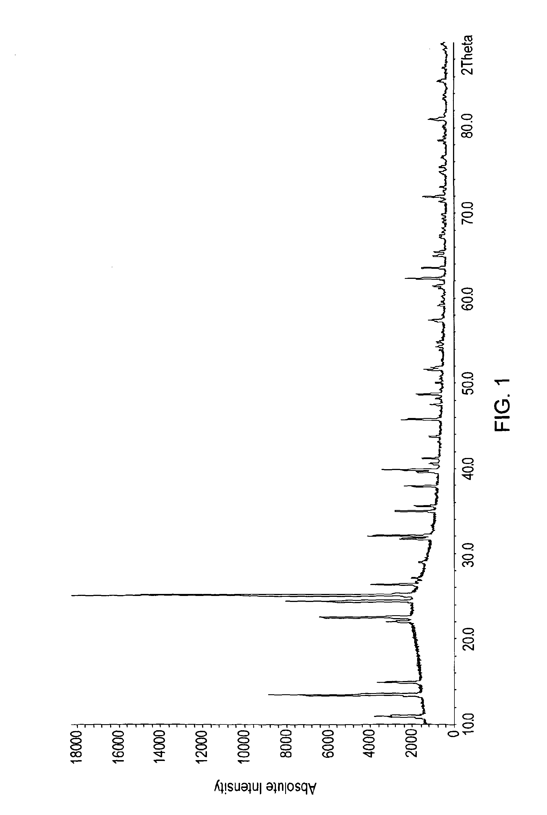
[0123]It was found that a phosphorus silicon oxide comprising Si5P6O25 and variants thereof could be formed simply by heating pyrophosphoric acid to between 230° C. and 250° C. for around 48 hours in a glass (Pyrex) vessel in a Dean Stark apparatus. Hydrogen peroxide was present and a catalytic amounts of ammonia (or sulfuric acid). SiO2 was leached directly from the glassware. Cooling and washing the resultant material (with methanol) to remove remaining catalyst affords silicon pyrophosphate materials of this family. This method is less preferred than synthetic Example 2 since it gives little control over the silicon content and clearly damages the reaction vessel. It does however serve to illustrate how easily phosphorus silicon oxide, and, in particular Si5P6O25 can be made. A number of other variant methods also proved successful

synthetic example 2

Solid State Method

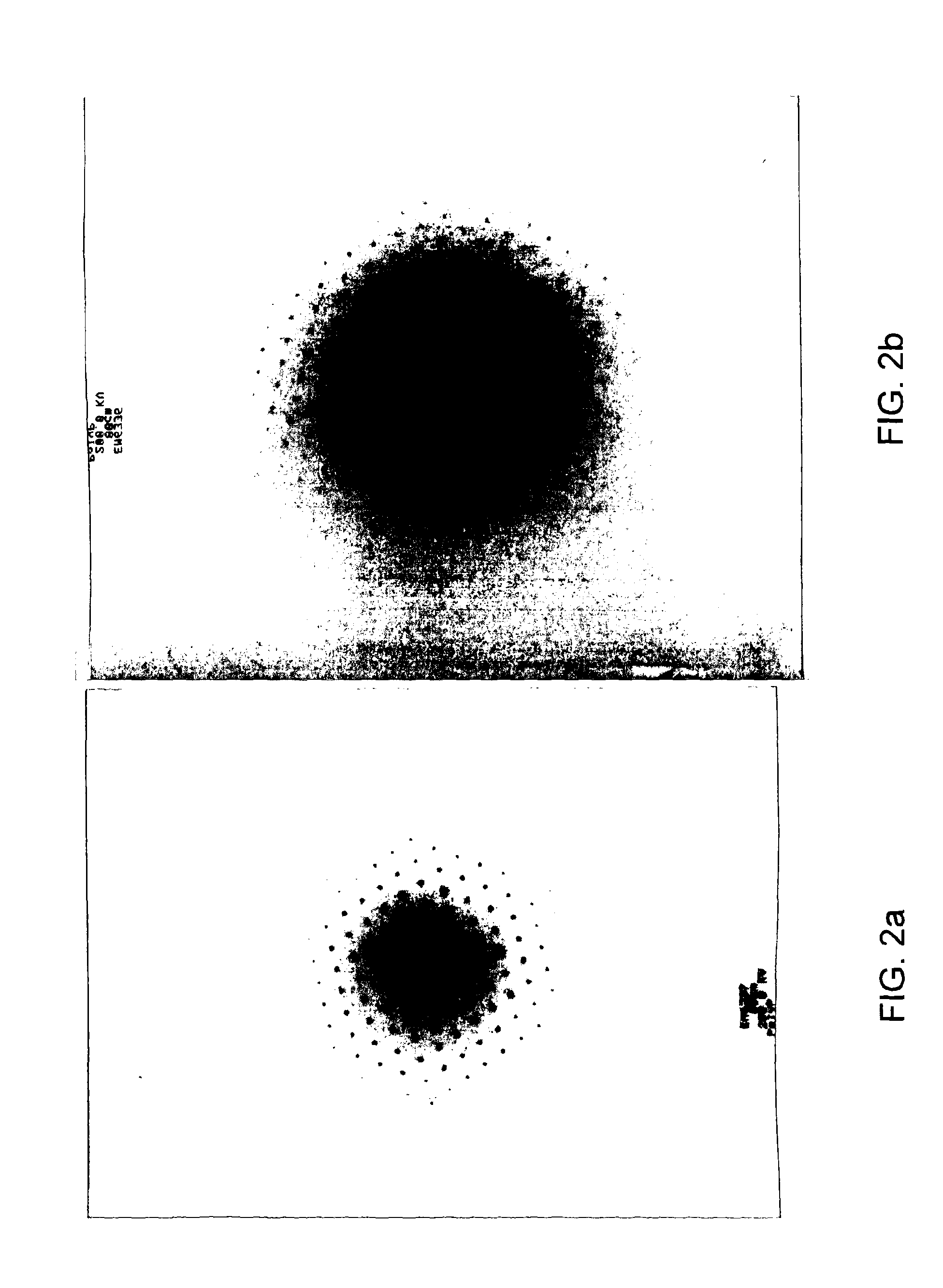
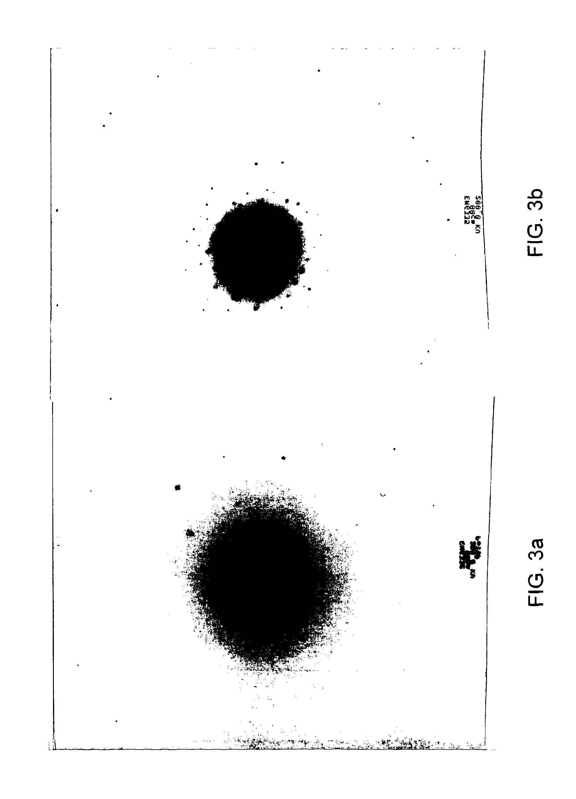
[0124]Very fine SiO2 powder (fumed silica) was dried for at least one hour at 800° C. to remove water and other absorbed gases prior to usage.

[0125]SiO2 and H4P2O7 were weighed in the relevant stoichiometric amounts (as per Table 1 below).

[0126]Ethanol was added to the SiO2 powder to prevent the loss of the very fine solid particles during mixing. A few drops of hydrochloric acid were added to the silica / ethanol to achieve partial hydrolysis of the mixture. The resulting mixture becomes a slurry on mixing.

[0127]Adding the pyrophosphoric acid and further mixing results in a gel-like slurry. Firing this gel-like slurry to 400° C. will then yield the Si5P6O25 and variant materials.

[0128]It is advantageous / convenient to introduce a lower temperature pre-firing stage to dry the gel-like slurry somewhat before final firing—the pyrophosphoric acid containing slurry / gel is highly corrosive. One should avoid its sudden exposure to high temperatures that may cause it to bubb...


PUM

PropertyMeasurementUnit
Temperatureaaaaaaaaaa
Timeaaaaaaaaaa
Humidityaaaaaaaaaa

Abstract

The invention provides a composition having the formula (I): xXO2.yY2O5, (wherein: 0.5<x<0.7; 0.3<y<0.5; X comprises one or more of silicon, titanium, germanium and zirconium; and Y comprises one or more of phosphorus, vanadium arsenic and antimony), or a hydrate thereof, in which the composition comprises more than 50 wt % or more of crystalline material.

Description

FIELD OF THE INVENTION[0001]The present invention relates to the use of phosphorus silicon oxide as an ionic conductor in a variety of electrochemical devices, in particular its use as a membrane in proton exchange membrane fuel cells, and to electrochemical devices comprising phosphorus silicon oxide as an ionic conductor.BACKGROUND OF THE INVENTION[0002]With oil reserves being depleted, the possibility of using fuel cells as an alternative means to provide electrical energy is attracting ever-increasing interest. Of the many types of fuel cell devised to date, proton exchange membrane fuel cells (PEMFCs) are of greater and greater potential with the world moving towards a hydrogen-based technology. PEMFCs can cleanly and efficiently convert the chemical energy of hydrogen and oxygen into water and electrical & thermal energy.[0003]In PEMFCs, hydrogen and oxygen react at separate electrodes—anode and cathode respectively—with the hydrogen being disassociated at the anode with the u...

Claims


Application Information

Patent Timeline
IPC IPC(8): H01M8/10C25B13/08G01N27/417H01M8/24C25B13/04B82Y30/00
CPCB01D67/0048Y02E60/521C01G23/047C01P2002/50C01P2002/72C01P2002/88C01P2004/03C01P2004/04C01P2004/61C01P2006/10C01P2006/40C08J5/2231H01M8/0291H01M8/1016C08J2343/00B01D2325/42B01D71/027H01M8/0289Y02E60/50
Inventor ATTIDEKOU, PIERROT SASSOUIRVINE, JOHN THOMAS SIRR
Owner UNIVERSITY OF ST ANDREWS
Learn More