High-Accuracy Mid-IR Laser-Based Gas Sensor

a gas sensor, high-accuracy technology, applied in the field of gas sensors, can solve the problems of inability to achieve the required accuracy level of ir spectroscopic sensor technology such as non-dispersed infrared absorption-based instruments, inability to add consumables, size and cost to the sensor, and inability to achieve the required accuracy level, etc., to achieve high accuracy, superior choice, and high accuracy

Inactive Publication Date: 2012-11-15
THERMO FISHER SCI BREMEN
View PDF9 Cites 140 Cited by
  • Summary
  • Abstract
  • Description
  • Claims
  • Application Information

AI Technical Summary

Benefits of technology

[0012]The present disclosure teaches various gas sensors for measuring, with high accuracy, the concentration of a given trace gas species in a gas sample. These gas sensors are based on optical absorption of middle infrared light that is specifically generated in a unique difference frequency generation (DFG) laser source. The laser source itself has numerous attributes that makes it a superior choice o

Problems solved by technology

Established IR spectroscopic sensor technologies such as non-dispersed infrared absorption-based instruments cannot achieve the required accuracy levels, because the presence of interferents, such as water vapor, confounds such measurements.
Moreover, many existing gas sensor systems employ cumbersome, ultra-high reflectivity optical multipass cells such as astigmatic Herriot or Cavity Ringdown cells in order to obtain measurements in the near infrared (0.7-3 μm), and are thus sensitive to optical contamination of the mirror surfaces that can result from commonly occurring trace level particulates and other contaminants.
Thus, although there presently exists an open-path methane sensor that operates in the near-infrared, it requires periodic cleaning of the mirror surfaces via rinsing the multipass cell optics with a solution while spinning the mirror at high speed, thereby adding consumables, size, and cost to the sensor.
Additionally, the size of this conventional sensor is not ideal, as local heating of the sample gas may occur.
Unfortunately, conventional diode lasers cannot be used directly in many important mid-IR spectrographic applicat

Method used


Image

  • High-Accuracy Mid-IR Laser-Based Gas Sensor
  • High-Accuracy Mid-IR Laser-Based Gas Sensor
  • High-Accuracy Mid-IR Laser-Based Gas Sensor

Examples


Embodiment Construction

[0053]The following description is presented to enable any person skilled in the art to make and use the invention, and is provided in the context of a particular application and its requirements. Various modifications to the described embodiments will be readily apparent to those skilled in the art and the generic principles herein may be applied to other embodiments. Thus, the present invention is not intended to be limited to the embodiments and examples shown but is to be accorded the widest possible scope in accordance with the features and principles shown and described. To appreciate the features of the present invention in greater detail, please refer to FIGS. 1-16 in conjunction with the following discussion.

System Configurations

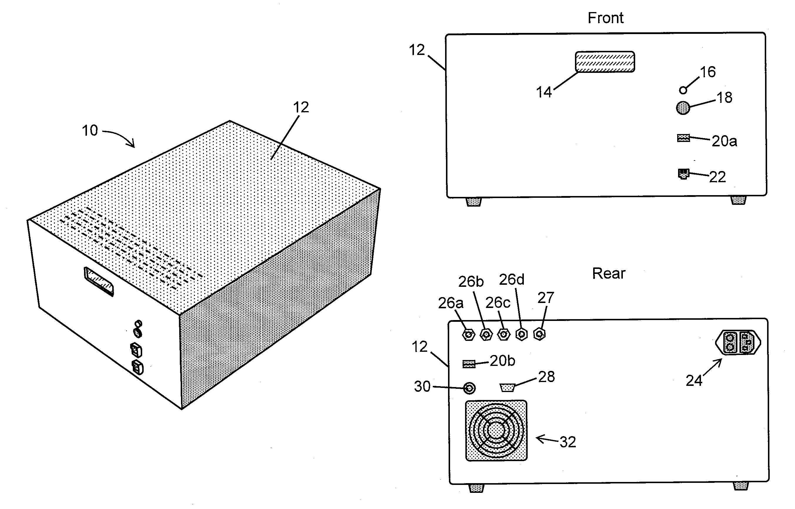
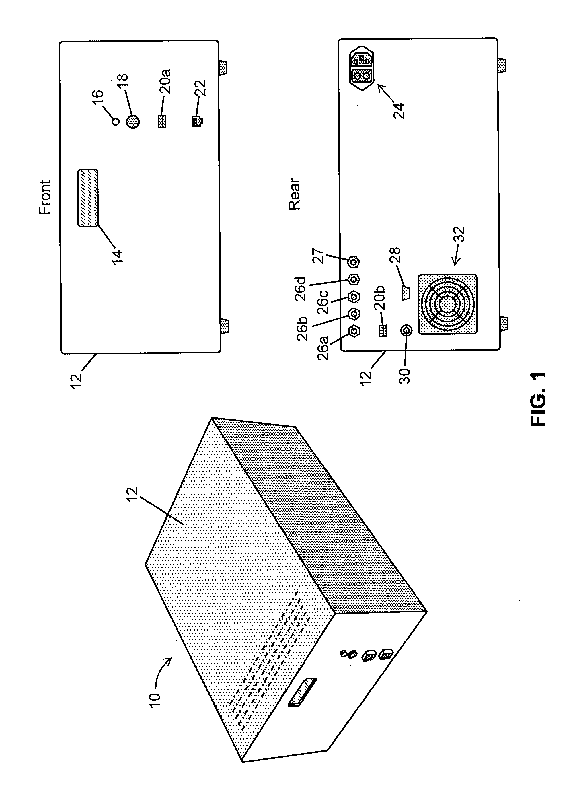
[0054]FIG. 1 is a set of external views—including perspective, front and rear views—of a gas sensor system in accordance with the present teachings. The illustrated gas sensor system 10 includes a chassis 12 that houses internal electronics, compute...


PUM


Abstract

A gas sensor system is provided, comprising: a gas cell operable so as to receive a sample gas; a vacuum system fluidically coupled to the gas cell operable to maintain the sample gas within the gas cell at a sub-ambient pressure; a pressure sensor operable to sense a pressure of the sample gas; a thermally insulated enclosure having the gas cell therein; a heat source or heat exchanger operable to influence an interior temperature of the thermally insulated enclosure; a light source within the thermally insulated enclosure operable to provide a mid-infrared (mid-IR) light into and through the gas cell; a photodetector within the thermally insulated enclosure operable to receive the attenuated mid-IR; and a control system electronically coupled to the vacuum system and to the pressure sensor operable to maintain the sample gas within the gas cell at the predetermined pressure to within one torr (1 Torr).

Description

CROSS REFERENCE TO RELATED APPLICATIONS[0001]This application is related to co-pending U.S. Provisional application No. 61 / 393,032, in the names of inventors James J. Scherer and Joshua B. Paul, filed Oct. 14, 2010 and titled “Single Frequency Tunable Middle Infrared Laser”. This application is also related to co-pending PCT Application No. ______ (Attorney Docket No. 5953W01 / PCT) titled “Optical Module Chamber Assembly” in the names of the inventors of the instant application and filed on even date herewith. The aforementioned co-pending applications are hereby incorporated by reference herein in their entirety as if set forth fully herein.FIELD OF THE INVENTION[0002]This invention generally relates to gas sensors for use in environmental air monitoring or industrial air monitoring and relates, more particularly, to such gas sensors that are capable of monitoring the variation, over time, of the concentration of a target gas species by measuring absorption of infrared light attribu...

Claims


Application Information

Patent Timeline
IPC IPC(8): G01N21/35G01N21/59
CPCG01N21/61G01N21/3504G01N21/031G01N21/39G01N33/0037G01N33/004Y02A50/20G01N21/0332G01N21/05
Inventor SCHERER, JAMES J.PAUL, JOSHUA B.JOST, HANS-JURG
Owner THERMO FISHER SCI BREMEN
Why Eureka
Try Eureka