Power electronics interconnection for electric motor drives

a technology of power electronics and electric motors, applied in the direction of laminated bus bars, electrical apparatus construction details, transportation and packaging, etc., can solve the problems of many potential inefficiencies in the distribution and conversion of electrical energy of electric vehicles, and the difficulty of adjusting to irregular shape volumes, so as to reduce the loss of interconnect resistance and reduce the inductance of the bus. , the effect of high performan

Active Publication Date: 2012-12-06
TESLA INC
View PDF8 Cites 50 Cited by
  • Summary
  • Abstract
  • Description
  • Claims
  • Application Information

AI Technical Summary

Benefits of technology

[0011]Embodiments of the present invention include one or more of a collection of features allowing a formed copper bus bar structure to be designed into an electric motor drive and the like. Prior implementations of a motor drive have not used a formed copper structure for connection of multiple discrete semiconductor devices with power electronics devices, such as, for example, a DC-Link and / or a snubber capacitor, gate drive reference voltages, DC bus connection, phase output connection, and the like. The included features make the use of the formed structure possible in a volume manufacturing environment and with very high performance.
[0012]Losses associated with interconnect resistance can be significantly reduced as are bus inductance(s). Lower bus inductance results in lower switching related losses in the semiconductors, and more importantly it reduces the voltage induced on the DC bus due to inductance-induced overshoot. Lower voltage overshoot allows the use of the most efficient semiconductor devices. The bus bar structures of the preferred embodiments are not required to be flat like conventional PCB assemblies, allowing for mounting flexibility in a semiconductor to heatsink interface.

Problems solved by technology

There are many well-known challenges to combining these technologies in a single operational circuit.
These challenges include mechanical design and layout of the components, to allow very large currents to be routed and controlled.
Generally these circuit boards are planar and can be difficult to conform to irregularly-shaped volumes.
There are many potential inefficiencies in an EV regarding distribution and conversion of electrical energy.
For many reasons, inductance is one limitation on fast switching times and reducing inductance generally reduces inefficiencies in an EV circuit, particularly the important propulsion and power storage / distribution circuits.

Method used


Image

  • Power electronics interconnection for electric motor drives
  • Power electronics interconnection for electric motor drives
  • Power electronics interconnection for electric motor drives

Examples


Embodiment Construction

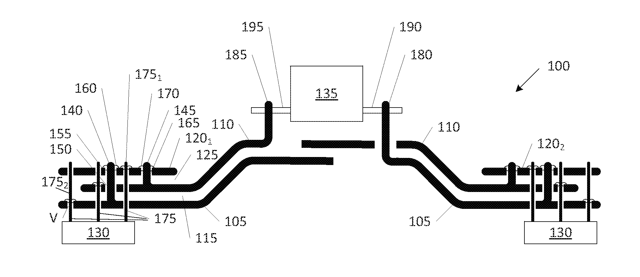
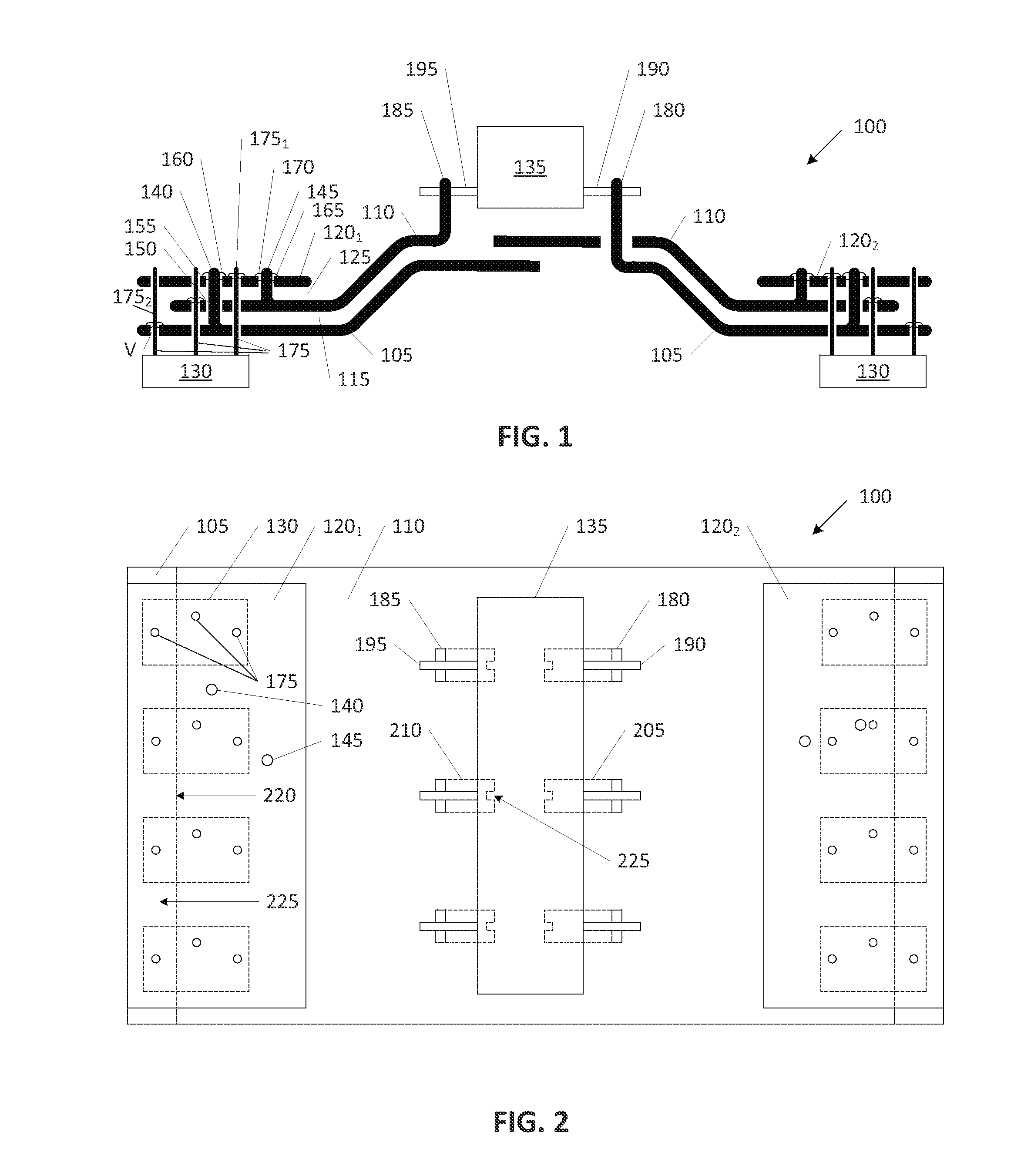
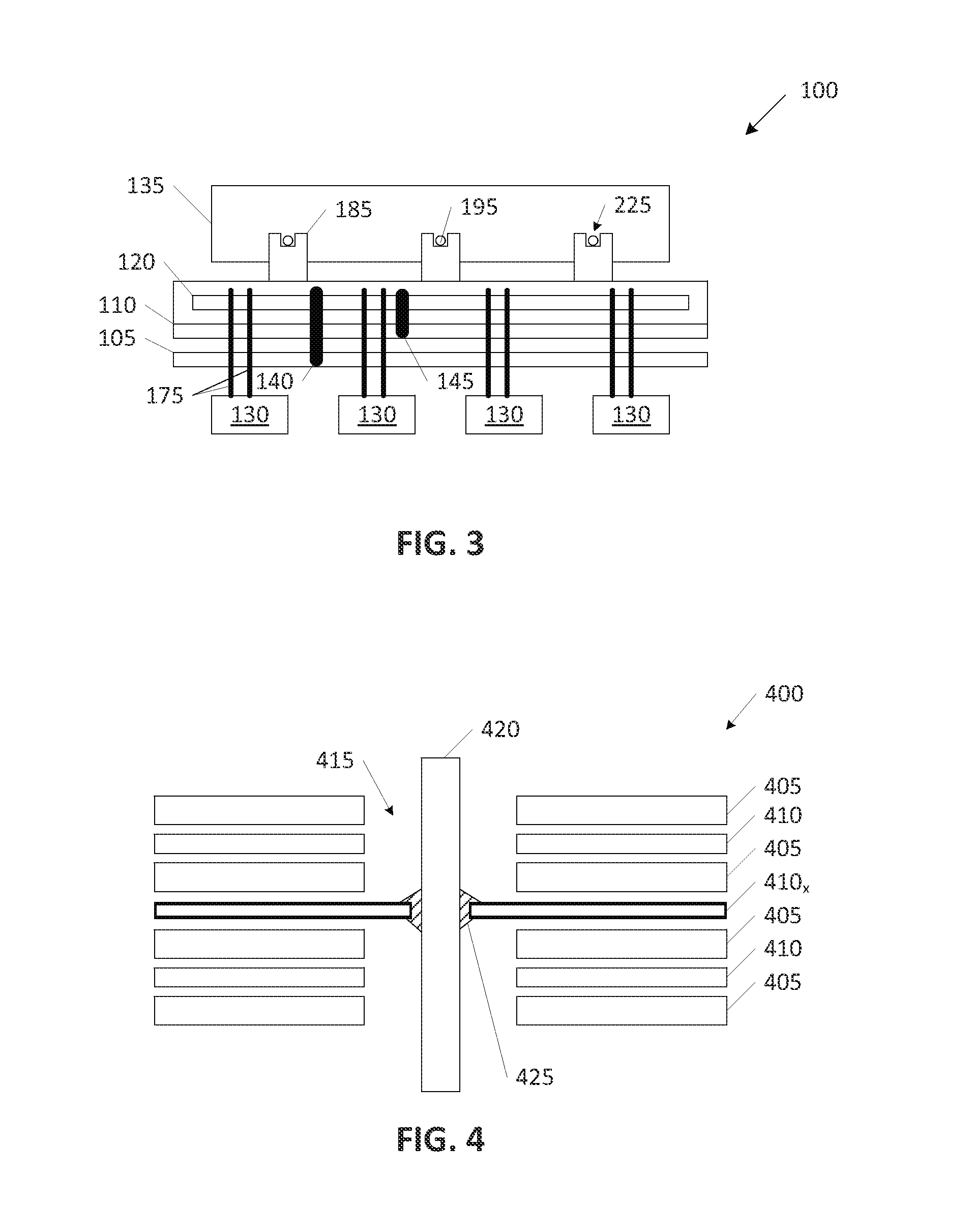
[0028]Embodiments of the present invention provide a specialized formable low inductance high current capacity bus bar blending power electronics and arrays of semiconductors and other devices into a single hybrid structure. The following description is presented to enable one of ordinary skill in the art to make and use the invention and is provided in the context of a patent application and its requirements. In the following text, the terms “energy storage assembly,”“battery,”“cell,”“battery cell,”“battery cell pack,”“electrolytic double-layer capacitor,” and “ultracapacitor” may be used interchangeably (unless the context indicates otherwise” and may refer to any of a variety of different rechargeable configurations and cell chemistries including, but not limited to, lithium ion (e.g., lithium iron phosphate, lithium cobalt oxide, other lithium metal oxides, etc.), lithium ion polymer, nickel metal hydride, nickel cadmium, nickel hydrogen, nickel zinc, silver zinc, or other charg...


PUM

PropertyMeasurementUnit
thicknessesaaaaaaaaaa
thicknessaaaaaaaaaa

Abstract

The bus bar includes a first bus bar layer formed of a first generally uniform thickness of a first bus bar conductor; a first dielectric layer overlying a top surface of the first bus bar layer; and a second bus bar layer formed of a second generally uniform thickness of a second bus bar conductor overlying a top surface of the first dielectric layer and the top surface of the first bus bar layer wherein: the first bus bar layer includes a first via for receipt of a first electrical lead of an electrical component and a second via for receipt of a second electrical lead of the electrical component and wherein: the first dielectric layer and the second bus bar layer each include a via aligned with the first via wherein the first electrical lead is extendable from beneath the first bus bar layer through the first dielectric layer and through the second bus bar layer.

Description

BACKGROUND OF THE INVENTION[0001]The present invention relates generally to formed copper bus bars, and more specifically, but not exclusively, to specialized bus bars and features thereof used to blend power electronics and arrays of semiconductors and other devices typically interconnected on circuit boards into a single hybrid structure.[0002]An electric vehicle (EV) incorporates a hybrid set of technologies throughout its various systems. For example, there is an energy storage system that stores and distributes large amounts of electrical energy. The storage and distribution is controlled using high-performance semiconductor devices for very fast switching to drive an electric motor, among other purposes. There are many well-known challenges to combining these technologies in a single operational circuit.[0003]These challenges include mechanical design and layout of the components, to allow very large currents to be routed and controlled. Bus bars in general are well-known for ...

Claims


Application Information

Patent Timeline
Patent Type & Authority Applications(United States)
IPC IPC(8): H02G5/00H01R43/00
CPCH05K7/1432Y10T29/4913Y10T29/49174H02G5/005H01B13/0036H02M7/003H02G5/00Y10T29/49224H01G9/26Y02T10/70H05K7/14329
Inventor KALAYJIAN, NICHOLAS ROBERTFERGUSON, JOSHUA WILLARDDETTMANN, BENJAMIN DAVIDKROEZE, RYAN CARTERKUBBA, MICHAEL RAJCHI, WILLIAM THOMAS
Owner TESLA INC
Why Eureka
Try Eureka