Photoelectric conversion element, dye-sensitized solar cell, metal complex dye, dye solution, dye-adsorbed electrode, and method for producing dye-sensitized solar cell

a technology of photoelectric conversion and solar cell, which is applied in the direction of ruthenium organic compound, sustainable manufacturing/processing, and final product manufacturing, etc., can solve the problems of inability to meet the requirements of high-efficiency photoelectric conversion, etc., to achieve excellent adsorption stability, improve photoelectric conversion efficiency, and increase the effect of optical absorption

Active Publication Date: 2015-09-03
FUJIFILM CORP
View PDF3 Cites 8 Cited by
  • Summary
  • Abstract
  • Description
  • Claims
  • Application Information

AI Technical Summary

Benefits of technology

[0091]According to the present invention, it is possible to provide a photoelectric conversion element and a dye-sensitized solar cell which have excellent adsorption stability onto the surface of semiconductor fine particles or durability as well as improved photoelectric conversion efficiency by increasing the optical absorption in a long wavelength region so as to improve the spectral sensitivity characteristics in the long wavelength region. In addition, it is possible to provide a metal complex dye, a dye solution and a dye-adsorbed electrode which are suitably used for these, and a method for producing dye-sensitized solar cell.
[0092]Other and further features and advantages of the invention will appear more fully from the following description, appropriately referring to the accompanying drawings.

Problems solved by technology

In particular, solar cells that make use of non-exhaustive solar energy do not necessitate fuels, and full-fledged practicalization of solar cells as an inexhaustible clean energy is being highly expected.
However, silicon is an inorganic material, and has its own limitations in terms of improving throughput and cost.
However, these proposals were not entirely satisfactory for an improvement in the photoelectric conversion efficiency and durability.

Method used


Image

  • Photoelectric conversion element, dye-sensitized solar cell, metal complex dye, dye solution, dye-adsorbed electrode, and method for producing dye-sensitized solar cell
  • Photoelectric conversion element, dye-sensitized solar cell, metal complex dye, dye solution, dye-adsorbed electrode, and method for producing dye-sensitized solar cell
  • Photoelectric conversion element, dye-sensitized solar cell, metal complex dye, dye solution, dye-adsorbed electrode, and method for producing dye-sensitized solar cell

Examples


example 1

Synthesis of Metal Complex Dye

[0357]Hereinafter, the synthetic method of the metal complex dye of the present invention will be described in detail, but starting substances, dye intermediates and synthetic routes are not limited to these.

Synthesis of metal complex dye D-1

[0358]The metal complex dye D-1 was synthesized according to the following scheme.

(i) Synthesis of Compound 3

[0359]In 62 ml of THF (tetrahydrofuran), 1 g of Compound 1 and 2.08 g of Compound 2 were dissolved. Thereto, 371 mg of Pd(PPh3)4 and 12.5 ml of a 2 N aqueous solution of potassium carbonate were added, and then the mixture was allowed to react at 80° C. over night. To the solution thus obtained, 100 ml of water, 40 ml of hexane, and 60 ml of ethyl acetate were added, and the liquid-liquid extraction was conducted. Thereafter, the organic layer was concentrated, and the crude product thus obtained was purified by silica gel column chromatography, thereby obtaining 1.59 g of Compound 3.

(ii) Synthesis of Compoun...

example 2

Dye-Sensitized Solar Cell

[0449]The dye-sensitized solar cell was fabricated in the following manner, and subjected to the measurement of IPCE (quantum yield) at 900 nm.

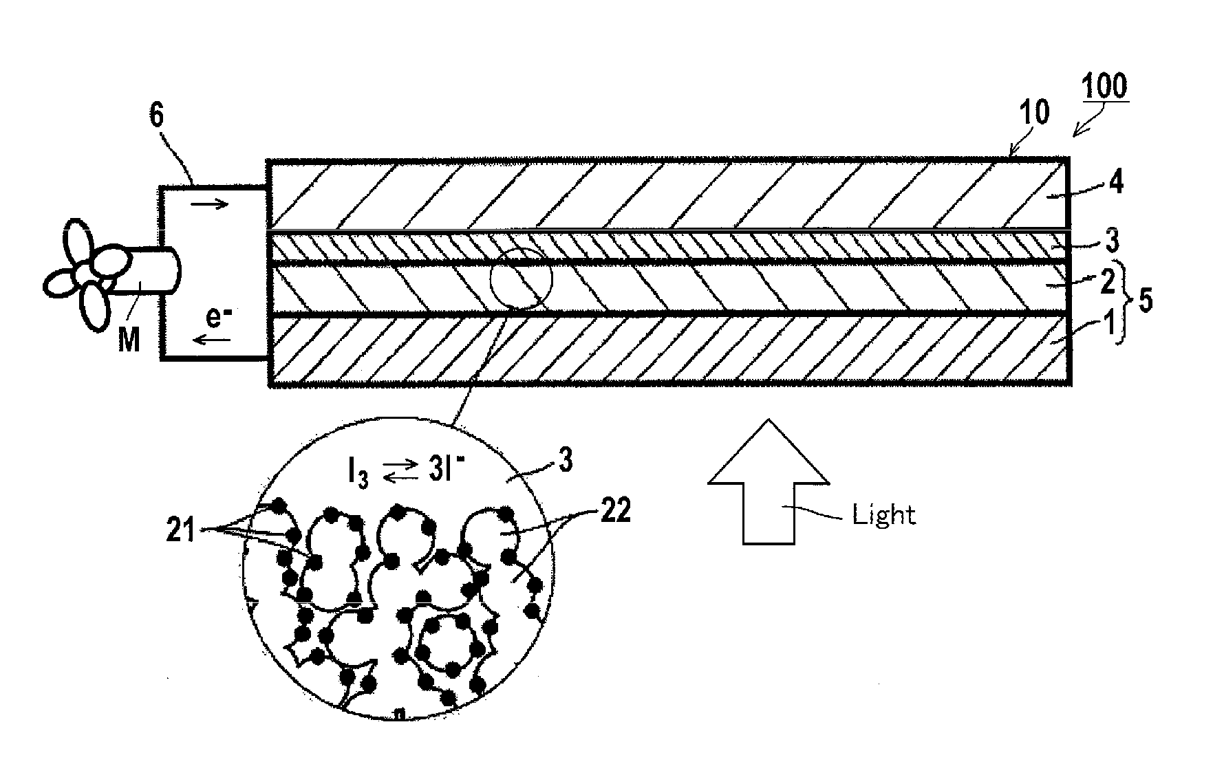
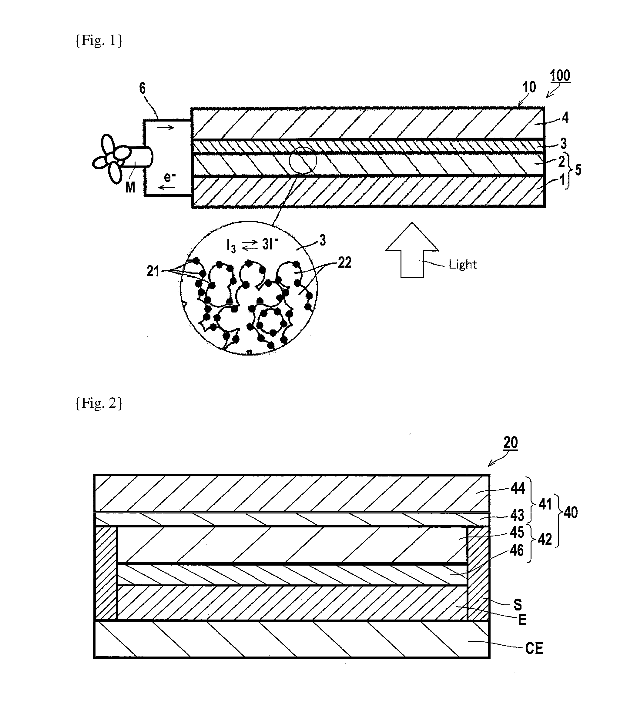
[0450]According to the procedure described below, a photoelectrode having the same configuration as that of the photoelectrode 12 shown in FIG. 5 of JP-A-2002-289274 was produced, and using the photoelectrode, a dye-sensitized solar cell 20 of a scale of 10 mm×10 mm having the same configuration as that of the dye-sensitized solar cell 20 shown in FIG. 3 of JP-A-2002-289274 except for the photoelectrode, was produced. The specific configuration thereof is shown in FIG. 2 attached to the present application.

[0451]In FIG. 2 of the present application, 41 denotes a transparent electrode, 42 denotes a semiconductor electrode, 43 denotes a transparent electrically-conductive film, 44 denotes a substrate, 45 denotes a semiconductor layer, 46 denotes a light-scattering layer, 40 denotes a photoelectrode, 20 denotes a dye-sen...

example 3

[0465]The adsorption stability of metal complex dye was evaluated in the following manner.

[0466]For evaluation of the adsorption stability (adsorptive power) of the metal complex dye onto the surface of semiconductor fine particles, titanium dioxide was used as the semiconductor fine particles, and the desorption rate of the metal complex dye from the surface of the titanium dioxide was used as an index.

[0467]The desorption rate of the metal complex dye was calculated by means of a Quartz Crystal microbalance with Dissipation monitoring (QCM-D) intermolecular interaction measuring apparatus E1 (manufactured by Meiwafosis).

[0468]Paste A (anatase, average particle size: 25 nm) was printed by screen printing (film thickness: 20 μm) on a gold sensor (manufactured by Meiwafosis) for use for the QCM-D. By calcining the thus-printed gold sensor at 450° C. for 1 hour in the air, a gold sensor having a semiconductor layer adsorbed thereon was prepared.

[0469]The thus-prepared sensor was insta...


PUM

PropertyMeasurementUnit
wavelengthaaaaaaaaaa
absorption wavelengthaaaaaaaaaa

Abstract

A photoelectric conversion element, having a photoconductor layercontaining semiconductor fine particles carrying a metal complex dye of Formula (I); a metal complex dye, a dye solution, a dye-adsorbed electrode, a dye-sensitized solar cell, and a method for producing the solar cell:
M(LA)(LD)(LX)mX·(CI)mY  Formula (I)
M represents a metal ion, LA represents a ligand of Formula (AL), LD represents a bidentate or tridentate ligand, at least one of coordinating atoms being an anion; LX represents a monodentate ligand; CI represents a counter ion; mX is 0 or 1; mY is 0 to 3;
Rings A to C represent a heterocycle; Z1 and Z2 represent a carbon or nitrogen atom; Anc1 to Anc3 represent an acidic group; X1 to X3 represent a single bond or linking group; R1 to R3 represent a substituent; l1, l3, l2, m1, m3, m2, n1, n2, and n3 each are an integer.

Description

CROSS-REFERENCE TO RELATED APPLICATIONS[0001]This application is a Continuation of PCT International Application No. PCT / JP2013 / 080883 filed on Nov. 15, 2013, which claims priority under 35 U.S.C. §119 (a) to Japanese Patent Application No. 2012-252700 filed on Nov. 16, 2012, Japanese Patent Application No. 2012-252701 filed on Nov. 16, 2012, Japanese Patent Application No. 2013-062895 filed on Mar. 25, 2013, Japanese Patent Application No. 2013-129046 filed on Jun. 19, 2013, Japanese Patent Application No. 2013-151149 filed on Jul. 19, 2013, Japanese Patent Application No. 2013-205533 filed on Sep. 30, 2013, and Japanese Patent Application No. 2013-235218 filed on Nov. 13, 2013. Each of the above applications is hereby expressly incorporated by reference, in its entirety, into the present application.TECHNICAL FIELD[0002]The present invention relates to a photoelectric conversion element, a dye-sensitized solar cell, a metal complex dye, a dye solution, a dye-adsorbed electrode, an...

Claims


Application Information

Patent Timeline
Patent Type & Authority Applications(United States)
IPC IPC(8): H01G9/20C09B57/10C07F15/00
CPCH01G9/2059C07F15/0053C09B57/10Y02E10/542C07D401/14C07F15/0046C07D409/14C07D495/04C07D213/55C07D213/57C09B19/00C09B21/00C09B23/005C09B23/0058C09B23/105C09B57/00C09B57/008C09B69/008H01G9/2031Y02E10/549Y02P70/50H10K85/344
Inventor WATANABE, KOUSUKETANI, YUKIOSASAKI, KOUITSUSATOU, HIROTAKATSUNA, KAZUHIROKOBAYASHI, KATSUMI
Owner FUJIFILM CORP
Why Eureka
Try Eureka