Eureka AIR delivers breakthrough ideas for toughest innovation challenges, trusted by R&D personnel around the world.

Thin, narrow tube and drawing apparatus and drawing method for manufacturing the same

Active Publication Date: 2015-10-22
NAT INST OF ADVANCED IND SCI & TECH
View PDF2 Cites 2 Cited by
  • Summary
  • Abstract
  • Description
  • Claims
  • Application Information

AI Technical Summary

Benefits of technology

The present invention relates to a thin, narrow tube for a biodegradable medical device. The invention provides a method for making a thin, narrow tube with good precision over its entire region in both the longitudinal and circferential directions, without changing the material composition of the base material. The thin, narrow tube has an improved deformation ratio and controlled biodegradation time. Additionally, the invention provides a method for making a thin, narrow tube with a higher thickness deformation ratio or width direction deformation ratio compared to existing methods, and with a higher corrosion speed or rate. The thin, narrow tube has a longitudinally spiral orientation structure that balances thickness reduction and width reduction. The drawing apparatus ensures constant pressure between the parts and maintains a constant distance between the apparatus and the round tube's surface. This results in a precise processing of the round tube with desired diameters and good precision over the entire region in the longitudinal and circferential directions.

Problems solved by technology

However, since the stent is semipermanently placed in a treated vascular disease site, there is a problem of recurrence of stenosis and the like.
However, as described in NPL 1, the biodegradable polymer has a weak “force to support a blood vessel”, and thus is insufficient to secure blood flow in a narrowed site.
However, it is difficult to control time (biodegradation time) for the magnesium material to disappear in vivo compared to that of a polymer.
Therefore, ductility is insufficient and breaking easily occurs in a stage of expanding a stent.
However, a method of changing a material composition one by one has poor mass production efficiency.
In addition, since the magnesium material has a lower tensile strength than an iron-based material or an aluminum-based material and has a hexagonal close-packed (hcp) structure, a slip system during deformation at room temperature is limited only to (0001), and the workability is extremely insufficient.
Therefore, in the related art, it is difficult to obtain a long, thin, and narrow magnesium tube (round tube) having a diameter of 2 [mm] or less, a thickness of 200 [μm] or less, a length of 500 [mm] or greater, and a dimensional precision of 0.15[%] or less, which is necessary to process a stent.
However, the dimensional precision is poor, and the obtained length also does not satisfy 100 [mm].
However, the extrusion method and the seam welding method are limited to a case of manufacturing a round tube having a relatively large tube diameter from the viewpoint of process limitations, or the dimensions of a processing object, die strength, and the like, and thus cannot be applied to a case of manufacturing a thin, narrow tube.
However, it is difficult to process a long round tube due to limitations on the dimensions of the chamber and the metal core.
Therefore, there is a problem in that the inner wall surface 213a cannot obtain dimensional precision.
However, in a case where the round tube 223 to be processed is a narrow tube or a long tube, there is a problem in that it is technically difficult to manufacture the plug support bar 222A having a strength applicable to the case.
However, since the direction of the plug 232 is easily changed and the inner wall surface 233a of the round tube cannot be supported with a uniform force, the dimensional precision of the inner wall surface 233a is inferior to that of the fixed plug drawing.
In addition, the processing force during the floating plug drawing is strong, and thus the round tube 233 may receive an excessive pressure during the processing and may be easily broken.
In addition, in a case where the inner diameter of the round tube 233 is 1 [mm] or less, it is technically difficult to manufacture the plug 232 having a shape applicable to the case.
Even when the plug can be manufactured, there is a problem in that handling is difficult.
As a result, it is difficult to process the round tube 243 after the mandrel drawing into a desired mesh-like shape using a laser or the like in order to form a stent.

Method used


Image

  • Thin, narrow tube and drawing apparatus and drawing method for manufacturing the same
  • Thin, narrow tube and drawing apparatus and drawing method for manufacturing the same
  • Thin, narrow tube and drawing apparatus and drawing method for manufacturing the same

Examples


first embodiment

Drawing Apparatus

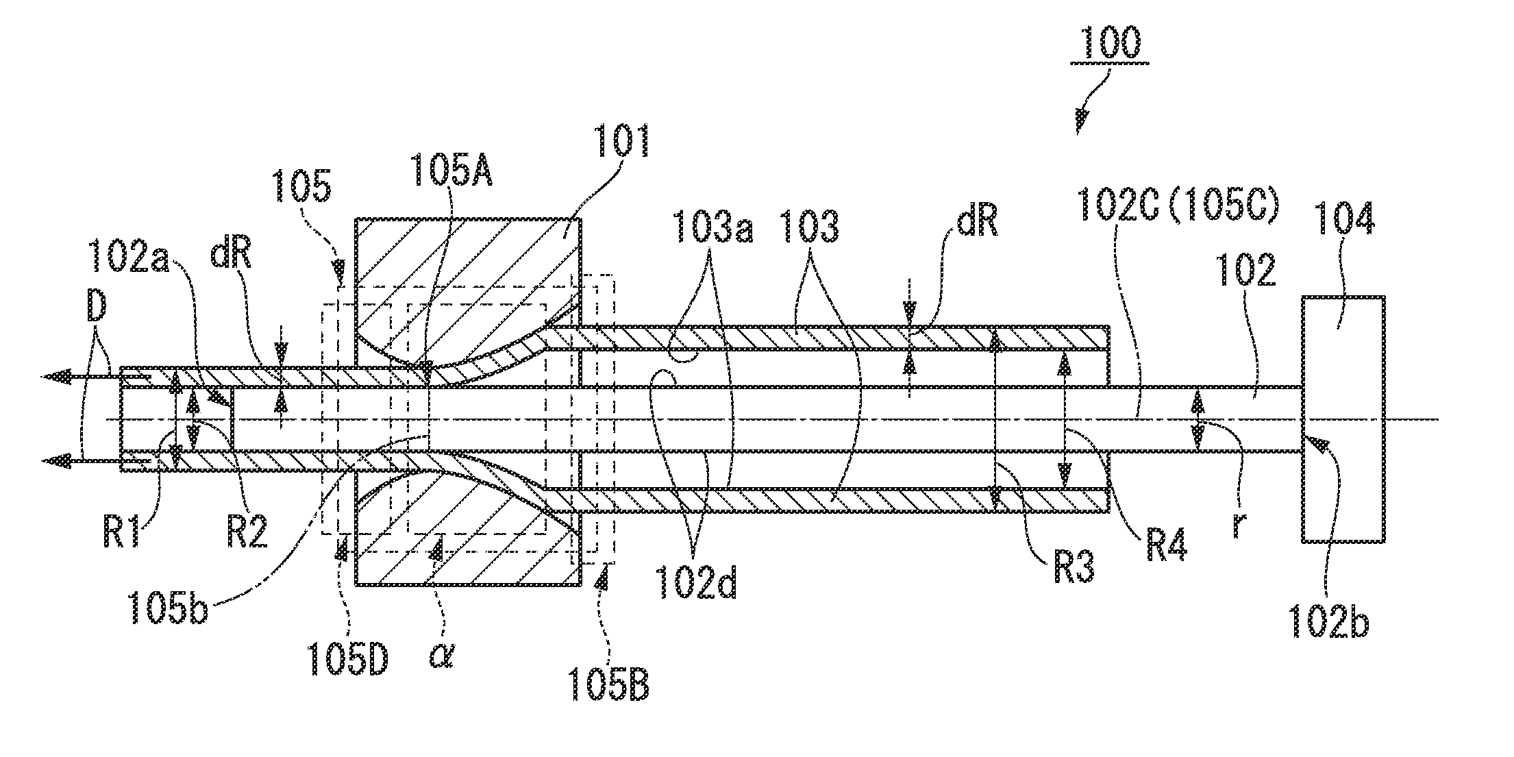
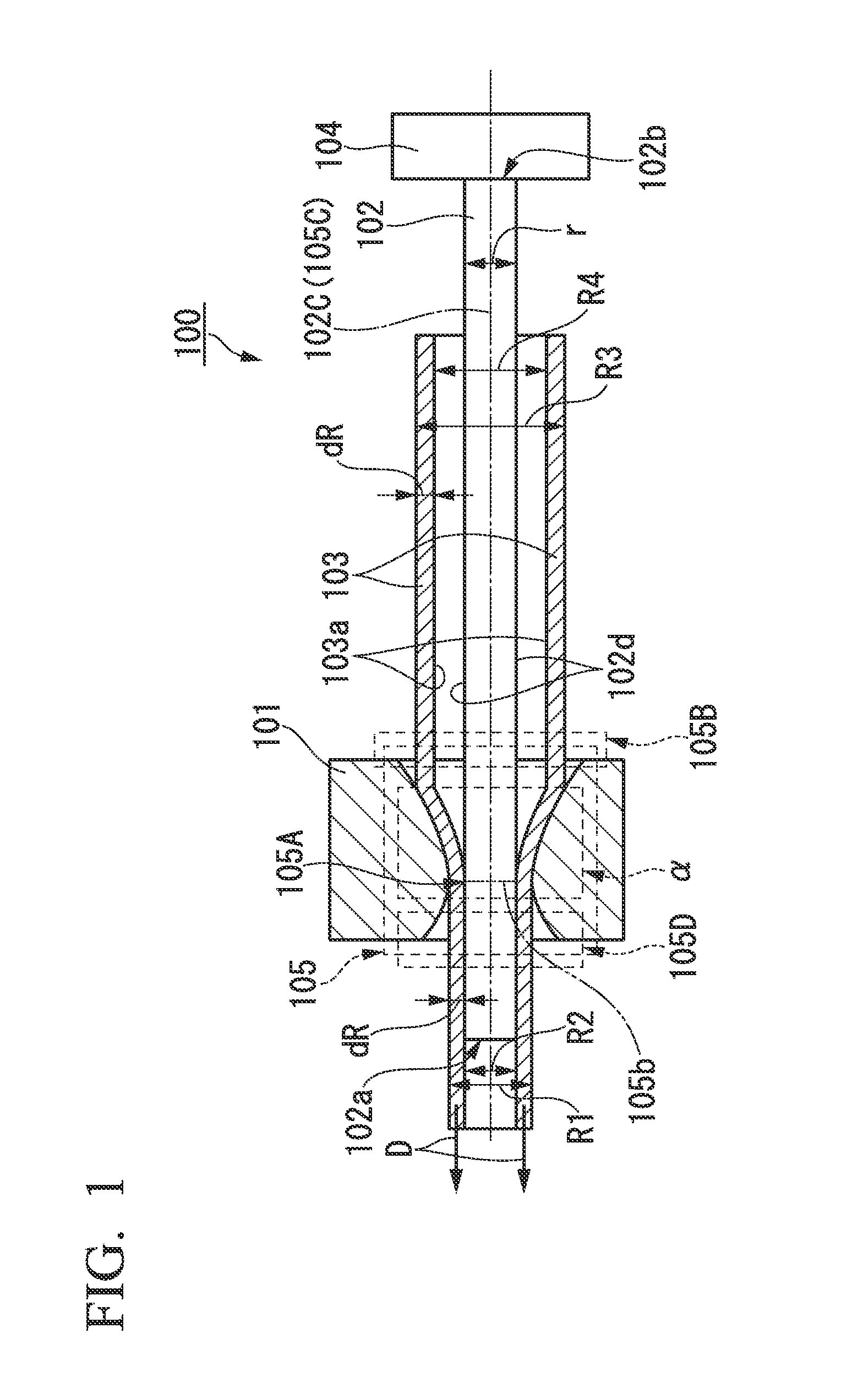
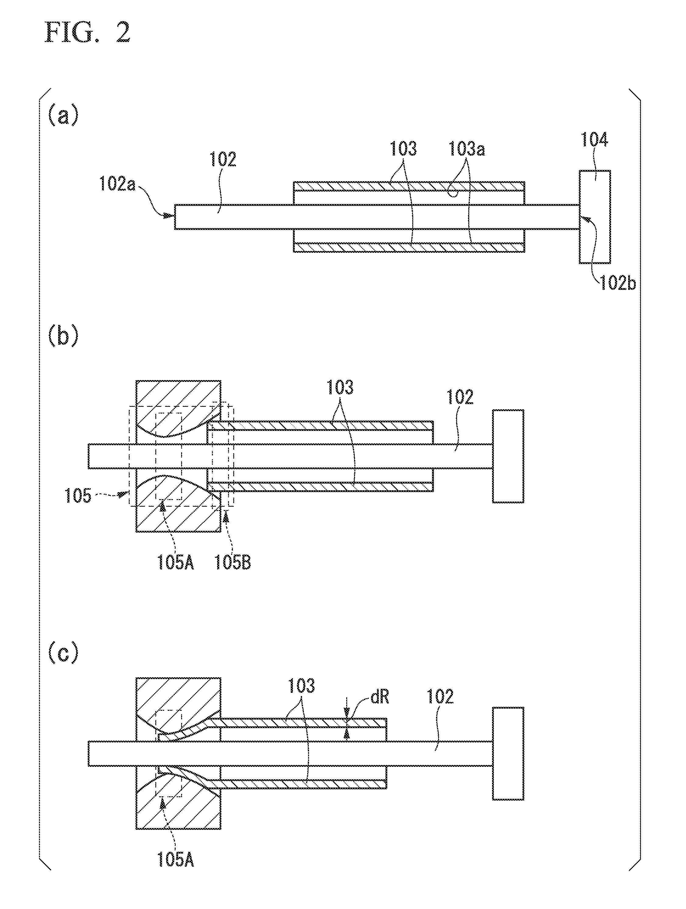
[0075]The configuration of a drawing apparatus of the present invention will be described. The drawing apparatus of the present invention includes at least first means, second means, and a fixing tool of the second means. The first means includes a part α which surrounds a round tube while being in contact therewith in a circumferential direction to reduce the diameter thereof. The second means has a cylindrical shape and is disposed to oppose a minimum inner diameter portion of the part α of the first means so that the side surface thereof supports the inner wall surface of the round tube.

[0076]In the above-described configuration of the drawing apparatus, an example of a case in which a die is used as the first means 101 and a mandrel is used as the second means 102 will be described with reference to FIG. 1. FIG. 1 is a cross-sectional view of a drawing apparatus 100 taken along a plane parallel to a drawing direction D of the round tube 103 to be processed. The ...

example 1

[0112]The Example 1 of the above-described drawing apparatus will be described. A crucible made of graphite for high-frequency induction heating, which accommodates a mixture of pure magnesium metal (350 [g]) and pure calcium metal (2.8 [g]) was placed inside a high-frequency coil in a high-frequency melting furnace chamber. Next, the inside of the chamber was evacuated, and then was filled with helium gas to atmospheric pressure. Subsequently, the crucible was heated to 750 [° C.] and then was held for 10 minutes after checking that the accommodated mixture was melted. Thereafter, the mixture (molten alloy) which was melted in the crucible was poured into a cylindrical type mold which was placed on the front surface of the high-frequency coil in advance. In addition, after cooling the resultant for a certain time, a cylindrical alloy ingot was obtained from the mold.

[0113]Next, the obtained alloy ingot was processed into a bar having an outer diameter of 17 [mm] through hot extrusi...

example 2

[0115]The Example 2 of the above-described drawing apparatus will be described. A crucible made of graphite for high-frequency induction heating which accommodates a mixture of pure magnesium metal (350 [g]) and pure calcium metal (2.8 [g]) was placed inside a high-frequency coil in a high-frequency melting furnace chamber. Next, the inside of the chamber was evacuated, and then was filled with helium gas to atmospheric pressure. Subsequently, the crucible was heated to 750[° C.] and then was held for 10 minutes after checking that the accommodated mixture was melted. Thereafter, the mixture (molten alloy) which was melted in the crucible was poured into a cylindrical type mold which was placed on the front surface of the high-frequency coil in advance.

[0116]In addition, after cooling the resultant for a certain time, a cylindrical alloy ingot was obtained from the mold.

[0117]Next, the obtained alloy ingot was processed into a bar having an outer diameter of 17 [mm] through hot extr...


PUM

PropertyMeasurementUnit
Fractionaaaaaaaaaa
Fractionaaaaaaaaaa
Angleaaaaaaaaaa

Abstract

Provided is a thin, narrow tube for use in a biodegradable medical device formed from a round tube made of a magnesium material as the base material, in which a desired outer diameter and an inner diameter are provided with good precision over the entire region in a longitudinal direction and a circumferential direction, and the length of biodegradation time can be controlled without changing a material composition. The thin, narrow tube is a thin, narrow tube of a biodegradable medical device, in which the thin, narrow tube is a round tube made of crystals containing magnesium (Mg) having a hexagonal crystal structure, and when the crystals forming the round tube are viewed in a round tube axis direction of the round tube, a hexagonal basal plane (0001) is oriented at a predetermined inclination angle with respect to a circumferential direction perpendicular to a radial direction (a direction from an inner surface to an outer surface) of the round tube.

Description

TECHNICAL FIELD[0001]The present invention relates to a thin, narrow tube, and a drawing apparatus and a drawing method for manufacturing the same. More specifically, the present invention relates to a thin, narrow tube which is appropriate for use in a biodegradable medical device represented by a stent, and a drawing apparatus and a drawing method for manufacturing the same.[0002]Priority is claimed on Japanese Patent Application No. 2012-173202, filed Aug. 3, 2012 and Japanese Patent Application No. 2013-157819, filed Jul. 30, 2013, the contents of which are incorporated herein by reference.BACKGROUND ART[0003]As an effective treatment method for coronary artery disease such as angina pectoris or myocardial infarction, there is a percutaneous coronary intervention (PCI). This is a treatment method performed using a catheter, and has become the mainstream of a coronary artery disease treatment after the 1990s due to an extremely low burden on a patient compared to that of other su...

Claims


Application Information

Patent Timeline
IPC IPC(8): A61F2/82A61L31/14B21C1/24A61L31/02
CPCA61F2/82A61L31/022A61F2210/0004B21C1/24A61L31/148A61L31/14C21D7/00C21D9/08C22F1/06C21D2201/05C22C1/02B21B17/04
Inventor HANADA, KOTAROMATSUZAKI, KUNIO
Owner NAT INST OF ADVANCED IND SCI & TECH
Why Eureka
Eureka Blog
Learn More