Reactor, CO2 sorbent system, and process of making H2 with simultaneous CO2 sorption

a co2 sorption and h2 technology, applied in the field of co2 sorbent system and process of making h2, can solve the problems of inability to build a large-scale h2 gas plant for distributed and/or on-demand power generation, inability to achieve the effect of reducing the size of the gas purification unit, reducing the psa, and reducing the reaction ra

Inactive Publication Date: 2016-10-20
BATTELLE MEMORIAL INST PNNL
View PDF4 Cites 10 Cited by
  • Summary
  • Abstract
  • Description
  • Claims
  • Application Information

AI Technical Summary

Benefits of technology

[0043]Li2CO3—CaO sorbent enhances yield from methane reforming and produces pure hydrogen during a first cycle as high as 99.8 vol %. However, capacity decreases with carbonation-regeneration cycles because the Li dopant escapes from the sorbent and the aged sorbent behaves like CaO, which is known to be unstable during the regeneration cycle.
[0047]The invention, in any of its aspects, can be characterized by one or more of the following: wherein the reaction channel comprising the steam reforming catalyst has an average diameter of 10 mm or less, or between 0.1 mm and 10 mm; preferably 0.5 mm and 5 mm; and wherein the reactor comprises a plurality of parallel reaction channels; preferably at least 10; more preferably at least 100; wherein the catalyst is a steam reforming catalyst and wherein the steam reforming catalyst is a wall coating and wherein an open bulk flow path is present in reaction channel; wherein the steam reforming catalyst comprises Ni, Cu, Mg, Ce, and Al; wherein the reactor comprises a honeycomb monolith; wherein the reactor comprises a plurality of parallel reaction channels alternating with plurality of parallel sorbent chambers; preferably at least 10 parallel reaction channels alternating with at least 10 parallel sorbent chambers; wherein sorbent fills a cross-section of the sorbent chamber; wherein the reactor channel or channels each have an inlet and an outlet; and wherein the sorbent chamber or sorbent chambers having no ports or closed ports such that gaseous flow into and out of sorbent chamber is only through the porous reaction channel wall(s); wherein the cross-section of the reaction channel (and / or sorbent chamber), in the direction orthogonal to flow through reaction channel, is square, rectangular, or circular; wherein the reactor comprises a honeycomb monolith; and wherein the monolith comprises: a macro- and meso-porous material (macroporous refers to pores in the range of 50 nm-100 μm; mesoporous 2 to 50 nm); a metal oxide; titania, alumina, silica; or a dense material such as metal with apertures for gas flow; wherein the sorbent surrounds the reaction channel; wherein a single sorbent chamber surrounds plurality of (preferably parallel) reaction channels; wherein the porous channel wall has a volume average pore size that in the range of about 1 nm to 100 μm, in some embodiments about 2 nm to 1000 nm. The sorbent in the reactor can be any of the sorbent compositions described herein. In some preferred embodiments, the reaction channel wall is not a membrane or a sorbent (in some preferred embodiments the reaction channel wall is inert) but is porous to all gases; this configuration provides for faster operation and greater stability.
[0054]The invention can also be characterized by any of the features or data provided in the descriptions or examples. For example, the sorbent could be characterized by the cycling test methods described in the examples while maintaining sorption capacity as shown in the examples. An example would be: wherein the CO2 sorbent is subjected to at least 8 regeneration cycles and the CO2 sorbent loses less than 5% of its sorption capacity; or wherein the CO2 sorbent is subjected to at least 8 regeneration cycles and the CO2 sorbent gains at least 5% of its sorption capacity. Furthermore, any aspect of the invention can, in some embodiments, be characterizable by any of the data from the examples ±10% or ±20%; either as a process characteristic or as a physical property when measured under the conditions described in the examples.Various embodiments of the invention can provide significant advantages. One innovative feature made possible by the inventive system is process equipment elimination and / or minimization compared to conventional hydrogen production. Bio-oil steam reforming (SR) is a highly endothermic reaction requiring significant amounts of heat. Heating the reactor tube in a furnace for SR or using partial oxidation (PDX) or auto-thermal reforming (ATR) are the conventional ways to supply the reaction heat. SR requires a large high-temperature furnace, while PDX and ATR need an air separation unit to supply oxygen. Both methods add complexity and cost. The inventive approach can utilize in-situ heating of the catalyst bed by alternating reforming (endothermic) and regeneration (exothermic) reactions, and by coupling of the endothermic reforming with exothermic carbonation reaction. This can eliminate an external combustor for SR or oxygen separator for PDX / ATR. Produced CO2 is captured in-situ with a solid sorbent that is integrated with the SR catalyst into one reactor.
[0055]Another innovative feature is minimization of process steps. In situ CO2 capture shifts thermodynamic equilibrium of SR reactions toward higher one-pass conversion to H2. Thus, a separate water-gas-shift (WGS) process step is avoided. And size of the gas purification unit such as pressure swing adsorption (PSA) can be reduced. The literature reactors typically operate at high temperatures (570-800° C.) presenting a challenging environment for sorbent stability. The invention can, in preferred embodiments, lower the reaction and CO2 capture temperatures to moderate regimes (<700° C.) using new reforming catalysts and CO2 sorbents.
[0056]Another innovative feature is to reduce catalyst deactivation, which is known as a major problem for reforming of bio-oils. Coverage of the catalyst pores by stagnant bio-oil liquids results in physical deactivation, while chemical deactivation is mostly due to coking of active sites. The physical deactivation can be mitigated by atomizing the bio-oil into small (<channel size) droplets using steam and / or by providing a smooth catalyst external surface to minimize accumulation of dead liquid pockets. The smooth surface of catalyst-coated monolith channel walls would enable uniform spread and contact of un-vaporized liquid droplets with the catalyst. The chemical deactivation is due to nature of catalysis chemistry. Bio-oils are comprised of some oxygenates that are potent catalyst coking agents. The deactivated catalyst is regenerated by burning off the coke. In the present invention, rapid swing reactor operation allows for catalyst deactivation by enabling frequent in-situ regeneration. As a result, the reforming reaction can be run at high space velocity and moderate temperatures on a highly active catalyst that deactivates. The swing reactor operation enables utilization of highly active catalysts that would not be possible in conventional steady-state reforming operations.

Problems solved by technology
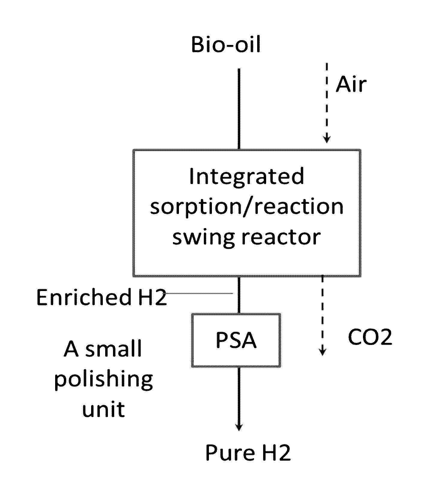
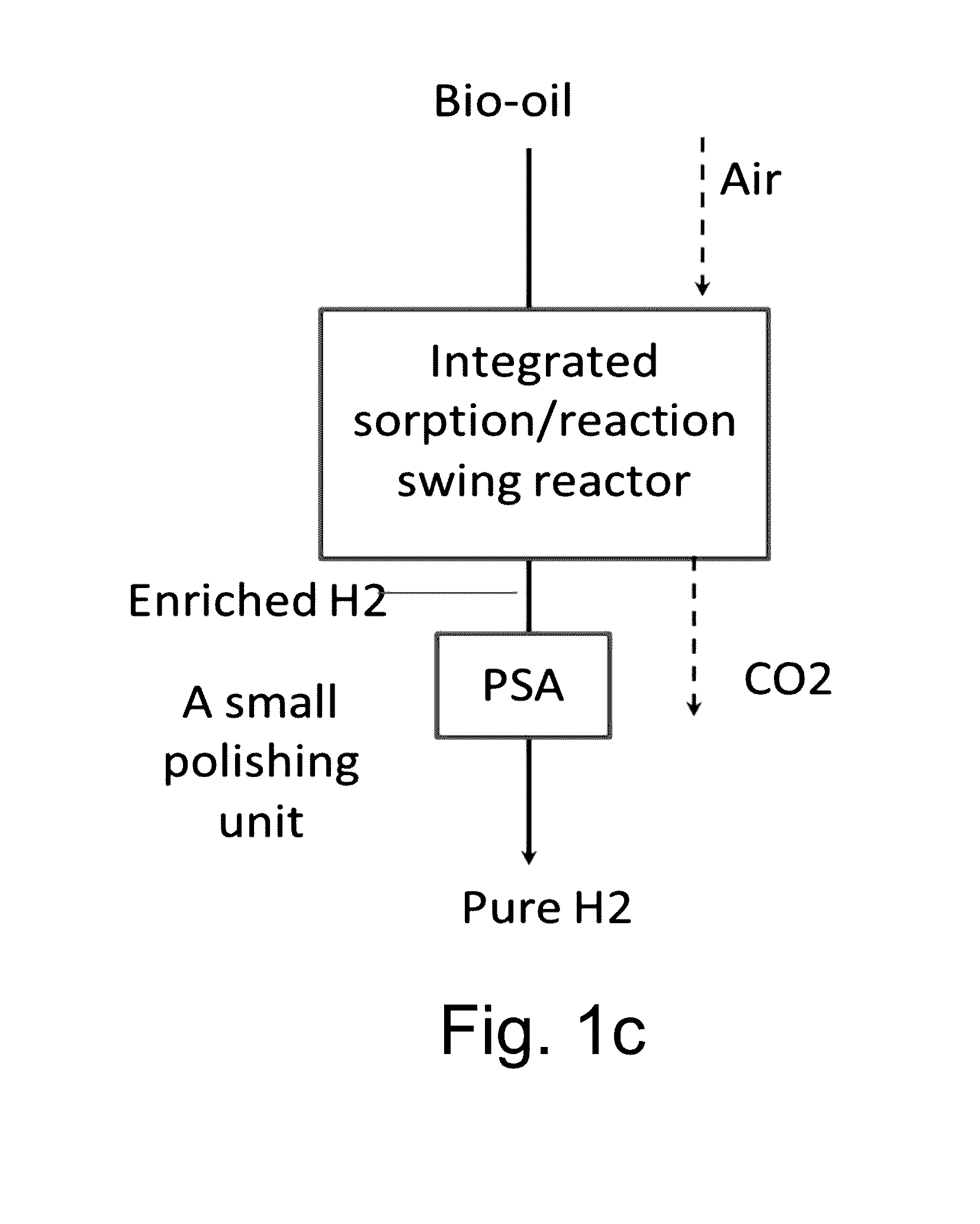
For example, it is not feasible to build conventional large-scale H2 gas plants for distributed and / or on-demand power generation using, e.g., H2 fuel cells, various H2-needed hydrogenation and / or hydrotreating processes, etc.
However, the reforming reaction is an energy-intensive process step because it is an endothermic reaction and involves a large capital cost.
In addition, process flow diagrams involving these conversion steps are too complicated to economically build a small-scale H2 plant, because economy of scale problems exist with conventional unit operation approaches.
Another problem is that catalysts often deactivate rapidly due to use of biomass-derived fuel sources.
However, unique challenges remain to be addressed for production of hydrogen from bio-oil compared to conventional hydrocarbon steam reforming processes.
However, stability of these newer catalysts has not been reported.
Further, reported steam / oil ratios in the literature are yet too high for practical application.
Reaction temperatures used in the literature are typically above 500° C. Catalyst deactivation is a prominent problem reported in most references.
And, long-term catalyst stability has not been achieved or reported in the literature, which is attributed to coke formation as a major cause.
One problem with this approach is degradation or de-activation of the sorbent in the presence of steam and over repeated sorption / regeneration cycles.
Another problem is about CO2 sorption and sorbent regeneration rates.
The slow kinetics of existing sorbent materials requires a large reactor vessel.
CaO-based sorbents are the most extensively studied one, because of in-expensive and abundant resources.
However, capacity decreases with carbonation-regeneration cycles because the Li dopant escapes from the sorbent and the aged sorbent behaves like CaO, which is known to be unstable during the regeneration cycle.
Furthermore, a stable CO2 sorbent has not yet been demonstrated in a sorption / regeneration cycle.

Method used


Image

  • Reactor, CO2 sorbent system, and process of making H2 with simultaneous CO2 sorption
  • Reactor, CO2 sorbent system, and process of making H2 with simultaneous CO2 sorption
  • Reactor, CO2 sorbent system, and process of making H2 with simultaneous CO2 sorption

Examples


example i

CO2 Sorbent Preparation

[0113]The dolomite-based composite sorbent was prepared in the following way. The Li2CO3—Na2CO3—K2CO3 eutectics (LiNaKCO3) has a melting point about 397° C. It was prepared by mixing 32.2 wt. % Li2CO3 (99%, Sigma Aldrich), 33.3 wt. % Na2CO3 (99%, Sigma Aldrich) and 34.5 wt. % K2CO3 (99%, Sigma Aldrich). The powder mixture was ground together and then heated to 410° C. for 1 hr. The resulting eutectic was crushed and ground to a fine powder. Dolomite from City Chemical was used as received of after calcination at 850° C. for 4 hours in air. The dolomite was mixed with LiNaK—CO3 at desired weight ratio by ball milling. The solid mixture was added into a Nalgene plastic bottle and mixed with 2-propanol (EMD Chemicals, Canada) and zirconia beads (diameter: 0.3-1.0 cm). The bottle was rotated at a speed of 150-200 rpm for 48-72 hours. The resulting slurry was dried at room temperature (RT) to allow evaporation of 2-propanol. Following drying, the cake was calcined ...

example ii

CO2 Sorption Performances by TGA Tests

[0116]Performance characteristics of sorbents for CO2 capture under steam-reforming conditions were tested on a thermo gravimetric analyzer (TGA, Netzsch Thermal Analysis, STA 409 cell) at ambient pressure. The sample weight for each test was approximately 20 mg. CO2 absorption was evaluated by heating sample in 10-100% CO2 to 500-600° C. Cyclic CO2 absorption and desorption were evaluated by exposing the sample to the CO2 gas for 50 minutes at 550° C. and then, raising the temperature in N2 flow and holding at 700° C. for 60 minutes. The gas flow rates for the sorption and regeneration processes were maintained at 70 ml / min and 90 ml / min, respectively. The heat of absorption was measured along with the TG tests through differential scanning calorimetry (DSC). The TGA tests help to identify CO2 sorption and regeneration temperatures, measure CO2 sorption capacity, and assess sorption and regeneration kinetics.

[0117]For comparison, performances o...

example iii

Packed Bed CO2 Sorption / Regeneration Tests of Composite Sorbents

[0126]A packed bed sorption test was conducted on a tube tubular reactor (316 stainless steel, 0.5″ OD, 0.049″ wall thickness). The sorbent particles of 40-100 mesh were loaded into the reactor tube by tapping the reactor wall. The resulting packing density was about 0.6 g / cc. The sorbent bed was held by quartz wool on the top and bottom. The gas flow was directed downward through the sorbent bed. Individual gas flow rates were controlled by mass flow controllers (MKS Instruments model 1179A and 1479A), while water flow rate was controlled by HPLC pump (Cole Parmer model DigiSense 89000). The bed temperature was controlled by the furnace heating. The sorbent bed was heated to 700° C. in 0.5 liter / min air to activate prior to lowering to designated sorption temperatures. The water was preheated to vaporize at 150° C. prior to entering the reactor. The reactor effluent was cooled down to 4° C. to condense the majority of ...


PUM

PropertyMeasurementUnit
diameteraaaaaaaaaa
diameteraaaaaaaaaa
volume average pore sizeaaaaaaaaaa

Abstract

A reactor and process for production of hydrogen gas from a carbon-containing fuel in a reaction that generates carbon dioxide is described. The carbon-containing fuel can be, for example, carbon monoxide, alcohols, oxygenates bio-oil, oil and hydrocarbons. In preferred embodiments, the reactor includes a monolithic structure form with an array of parallel flow channels. Methods of using the reactor are also described. In the reactor apparatus of the present invention, the catalytic reaction for hydrogen formation is conducted in conjunction with a carbonation reaction that removes carbon dioxide that is produced by the reactor. The carbonation reaction involves reaction of the carbon dioxide produced from the hydrogen formation reaction with metal oxide-based sorbents. The reactor apparatus can be periodically regenerated by regeneration of the sorbent. A carbon dioxide sorbent system comprising a solid sorbent and a eutectic, mixed alkali metal molten phase is also described.

Description

RELATED APPLICATIONS[0001]This patent application claims the priority benefit of U.S. Patent Application Ser. No. 62 / 109,840.INTRODUCTION[0002]Distributed hydrogen production has been sought to address a range of applications where pipeline hydrogen is not available. For example, it is not feasible to build conventional large-scale H2 gas plants for distributed and / or on-demand power generation using, e.g., H2 fuel cells, various H2-needed hydrogenation and / or hydrotreating processes, etc.[0003]Hydrogen production typically involves steam-reforming, water-gas-shift reactions, and gas purification steps. However, the reforming reaction is an energy-intensive process step because it is an endothermic reaction and involves a large capital cost. In addition, process flow diagrams involving these conversion steps are too complicated to economically build a small-scale H2 plant, because economy of scale problems exist with conventional unit operation approaches. Another problem is that ca...

Claims


Application Information

Patent Timeline
Patent Type & Authority Applications(United States)
IPC IPC(8): C01B3/40B01J23/83B01J20/04B01J7/02C01B3/56
CPCC01B3/40B01J7/02C01B3/56B01J20/043C01B2203/1235C01B2203/0233C01B2203/0475C01B2203/042C01B2203/1058B01J23/83C01B3/38C01B2203/0283C01B2203/0425C01B2203/1023C01B2203/1041C01B2203/1076C01B2203/1247B01J2219/243B01J19/2485B01J8/0242B01J2208/00274B01J2208/00309B01J2208/025B01J2219/2428B01J2219/2448B01J2219/2414Y02P20/145Y02P20/52B01J37/06B01J37/08B01J21/063B01J23/002B01J23/755B01J35/002B01J35/04B01J35/1014B01J35/1019B01J35/1038B01J37/0201B01J2523/00B01J2523/17B01J2523/22B01J2523/31B01J2523/3712B01J2523/847B01J2523/13
Inventor LIU, WEILI, XIAOHONG SHARI
Owner BATTELLE MEMORIAL INST PNNL
Why Eureka
Try Eureka