Separator For Use in Electrochemical Cells and Method of Fabrication Thereof

a technology for separation devices and electrochemical cells, which is applied in the direction of cell components, electrical equipment, cell component details, etc., can solve the problems of insufficient safety protection against thermal runaway events, complex manufacturing process, and standard commercial separators not optimized for high-rate battery applications, so as to improve the safety and electrochemical performance of secondary batteries, and improve the ability of high-rate and power density performance of secondary batteries. , the effect of reducing the cost of production

Inactive Publication Date: 2017-09-14
GINER INC
View PDF8 Cites 35 Cited by
  • Summary
  • Abstract
  • Description
  • Claims
  • Application Information

AI Technical Summary

Benefits of technology

[0011]This invention has several advantages. For example, the heat-resistant separator of the electrochemical cell of the invention can withstand temperatures far in excess of those generally available. Further, the heat-resistant separator can be fabricated efficiently and can be in the form of a laminate. The heat-resistant separator improves both safety and electrochemical performance of secondary batteries, including lithium-ion (Li-ion) batteries, such as by protecting against off-normal thermal abuse conditions and internal shorts from dendrite formation. The heat-resistant separator also provides improvements in high-rate and power density performance capabilities of secondary batteries.

Problems solved by technology

Li-ion batteries are currently the most promising power source technology for electric vehicles because of their improved volumetric and gravimetric energy density, and operating voltage range compared to nickel- and lead acid-based batteries.1-3 With increasing advances in achieving higher energy density, safety remains a major performance challenge for Li-ion batteries.
Major drawbacks of these separators include their complex manufacturing process and insufficient safety protection against thermal runaway events during off-normal abuse conditions.
Furthermore, standard commercial separators are not optimized for high-rate battery applications such as fast charging, fast discharging, or high rate pulse discharging.
Tri-layer separators (PP / PE / PP) are designed with a shutdown protection feature activated by a low-temperature melting PE middle layer when temperature reaches ˜130° C.7,8 Because tri-layer shutdown separators were originally designed for small format cells for consumer electronics, their abuse tolerance and shutdown feature are not reliable in larger format cells (>10 Ah) used in electric vehicles.
Additionally, these materials do not provide thermal runaway protection at elevated temperatures beyond the melting point of PP (T˜165° C.).
Furthermore, despite the inherent superior thermal stability of the ceramic particle additives, the maximum service temperature of ceramic separators is still limited by the melt integrity of the polymer binder used to form ceramic coating or impregnation composite layers.

Method used

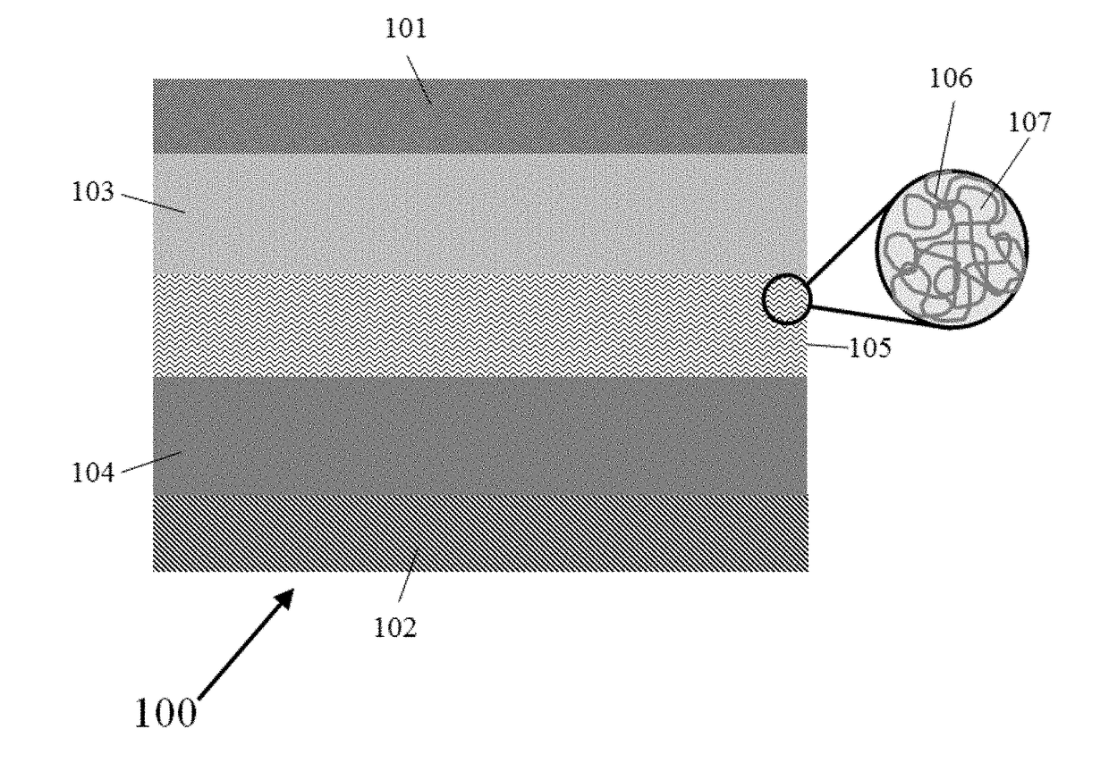
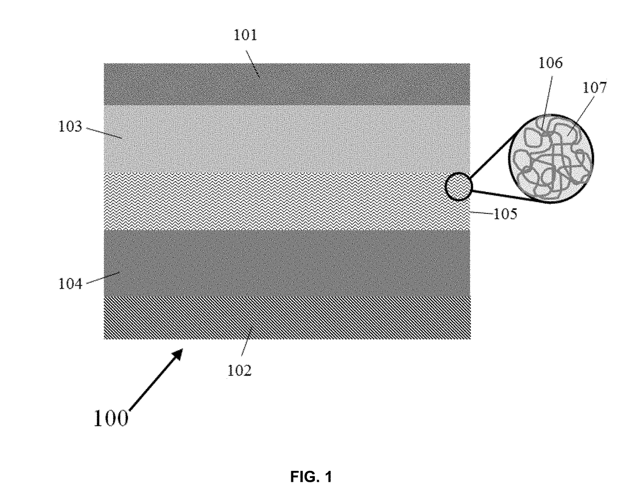
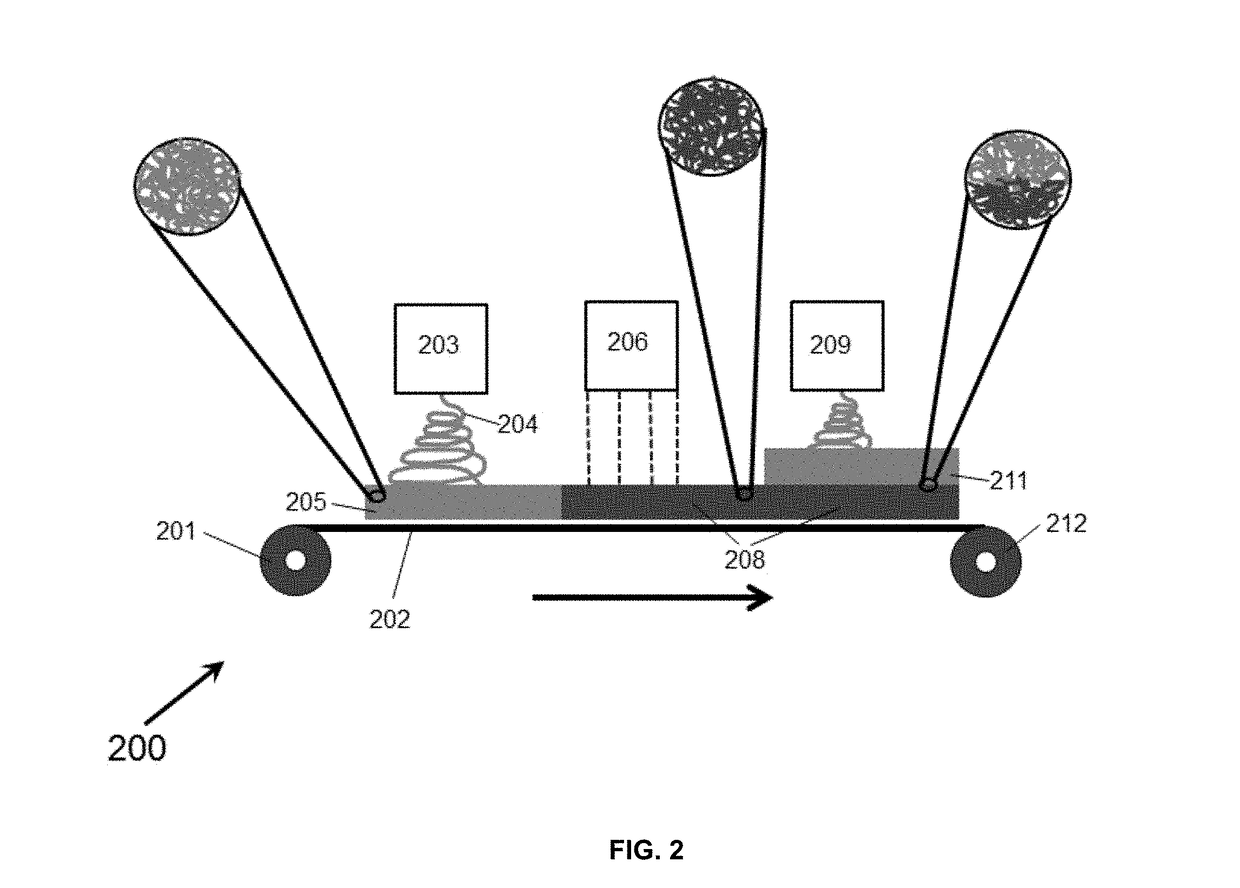

Image

  • Separator For Use in Electrochemical Cells and Method of Fabrication Thereof
  • Separator For Use in Electrochemical Cells and Method of Fabrication Thereof
  • Separator For Use in Electrochemical Cells and Method of Fabrication Thereof

Examples


example 1

[0059]1a. Fabrication of Heat-Resistant Separator.

[0060]EB-crosslinked NF separators were prepared by electrospinning acetone solution mixtures of PVdF-co-HFP (product no. Solef 21508 from Solvay; polymer concentration was 9 wt %) copolymer and triallyl isocyanurate (TAIC; 0, 5, 7.5, and 10 wt % relative to the weight of the polymer) cross-linker, under a high-voltage electric field (25 kV). The electrospinning solution also contained NaI (0.1 wt % relative to total weight of solid polymer). A needle-based electrospinning machine was used for nanofiber production. A solution feed rate of 0.05 mL / min and gap distance of 10 cm between emitter and collector electrode were used during the electrospinning manufacturing process. FIGS. 5A-5C show the manufactured NF materials consisting of flexible, nonwoven membranes with uniform fiber size. The fiber size distribution, determined using FibraQuant™ fiber analysis software, is d ˜223 nm (±63 nm). Cross-linking of the manufactured NF membra...

example 2

Electrochemical Evaluation of NF Separator.

[0067]2a. Continuous Rate Evaluation

[0068]To demonstrate the impact of improved ionic conductivity on battery cell performance, the rate capability of cells with NF separator was benchmarked against “Comparative Sample 1” separator. Rate tests were done on high-voltage, LiNi0.5Mn1.5O4 (LNMO) cathode cells built with two types of anodes (lithium metal and graphite carbon). Cells built with a Li anode are referred to as “half-cells”, while cells containing carbon anodes are referred to as “full-cells.” Continuous rate tests were done by charging cells under a constant-current (CC) to 100% state-of-charge (SOC) at a C / 4 (4-hr) rate, and then continuously discharging at varying rates from C / 5 (5-hr) to 8 C (8 min). The charge-discharge voltage window for the LNMO cells was 5 V to 3 V. FIGS. 11A, 11B and FIGS. 12A, 12B show that the EB-crosslinked separator provides a clear advantage over “Comparative Sample 1” in terms of improved capacity rete...


PUM

PropertyMeasurementUnit
porosityaaaaaaaaaa
sizeaaaaaaaaaa
diameteraaaaaaaaaa

Abstract

An electrochemical cell, such as a capacitor or a secondary battery, is formed with a heat-resistant separator comprising a crosslinked membrane. The heat resistant separator is formed by exposing a polymeric membrane to a suitable condition, such as electron beam irradiation, to form the cross linked separator. In certain embodiments, the heat-resistant separator can be in the form of a laminate. In other embodiments, the heat-resistant separator includes inorganic particulate additives. The separator improves both safety and electrochemical performance of electrochemical cells, including lithium-ion batteries, such as by protecting against off-normal thermal abuse conditions and internal shorts from dendrite formation. The heat-resistant separator also provides improvements in high-rate and power density performance capabilities of secondary batteries.

Description

RELATED APPLICATION[0001]This application claims the benefit of U.S. Provisional Application No. 62 / 305,158, filed on Mar. 8, 2016. The entire teachings of the above application are incorporated herein by reference.GOVERNMENT SUPPORT[0002]This invention was made with government support under DOD SBIR Phase I Contract No. HQ0147-14-C-8306 from the Department of Defense, Defense Logistics Agency. The government has certain rights in the invention.FIELD OF THE INVENTION[0003]This invention relates to a separator for use in electrochemical energy storage batteries, cells, and methods of preparing the separator.BACKGROUND OF THE INVENTION[0004]Electrochemical cells, such as capacitors and secondary batteries (e.g., lithium-ion batteries, lithium-sulfur batteries, and lithium-air batteries), are attractive for many commercial applications such as aerospace, automotive, medical devices, and portable electronics because of their desirable volumetric and gravimetric energy density performanc...

Claims


Application Information

Patent Timeline
Patent Type & Authority Applications(United States)
IPC IPC(8): H01M2/16H01G11/52H01G11/84H01M2/14H01M50/403H01M50/417H01M50/42H01M50/423H01M50/426H01M50/454H01M50/491H01M50/497
CPCH01M2/1686H01M2/162H01M2/1653H01G11/84H01M2/145H01G11/52H01M2/166H01M10/0525Y02E60/10H01M50/403H01M50/44H01M50/446H01M50/417H01M50/454H01M50/491H01M50/426H01M50/42H01M50/497H01M50/423Y02E60/13
Inventor LAICER, CASTROMOREIRA, MARIOHARRISON, KATHERINE
Owner GINER INC
Why Eureka
Try Eureka