
Flexible conducting cover glass replacement for satellite solar panels

a solar panel and flexible technology, applied in semiconductor devices, photovoltaic energy generation, coatings, etc., can solve the problems of inferior conductivity to prevent charge build-up from ambient radiation and thruster plumes, solar cells in space present additional challenges, and reduce the volume required for compartmentalizing solar arrays within vehicles, maximizing inherent properties, and reducing the effect of volume required

Inactive Publication Date: 2018-01-04
CELEVATOR PHILLIP +2
View PDF1 Cites 0 Cited by
  • Summary
  • Abstract
  • Description
  • Claims
  • Application Information

AI Technical Summary

Benefits of technology

The invention provides a composition for covering satellite solar panels that has improved properties and can extend the life span of the solar panel. The composition includes an encapsulating resin, a conductive nano-network, and fused silica / quartz beads mixed at a specific ratio to maximize its inherent properties. The composition is flexible and conductive, which makes it ideal for use in various applications such as a sensor to detect damage from space debris or a replacement for touchscreen material. The composition can be produced using a chemical vapor transport method or a vapor transport method.

Problems solved by technology

The use of solar cells in space presents additional challenges for composition of the cover glass material that are unique to space applications and which are not addressed by the types of cover glass used in terrestrial applications.
However, incorporation of this type of solar cell array into the standard rigid panel substrate and cover glass design essentially cancels out any advantages with regard to flexibility and mass associated with the IMM.
Cover glass materials that are commonly used on flexible solar arrays, for example, ITO and AZO are relatively transparent in terms of optical transmittance, but are associated inferior conductivity to prevent charge build-up from ambient radiation and thruster plumage.
However, the costs are high due to the complex circuitry and processing in order to make a conductive polymer.

Method used


Image

  • Flexible conducting cover glass replacement for satellite solar panels
  • Flexible conducting cover glass replacement for satellite solar panels
  • Flexible conducting cover glass replacement for satellite solar panels

Examples


example 1

of Zinc-Oxide Tetrapods or Agglomerates

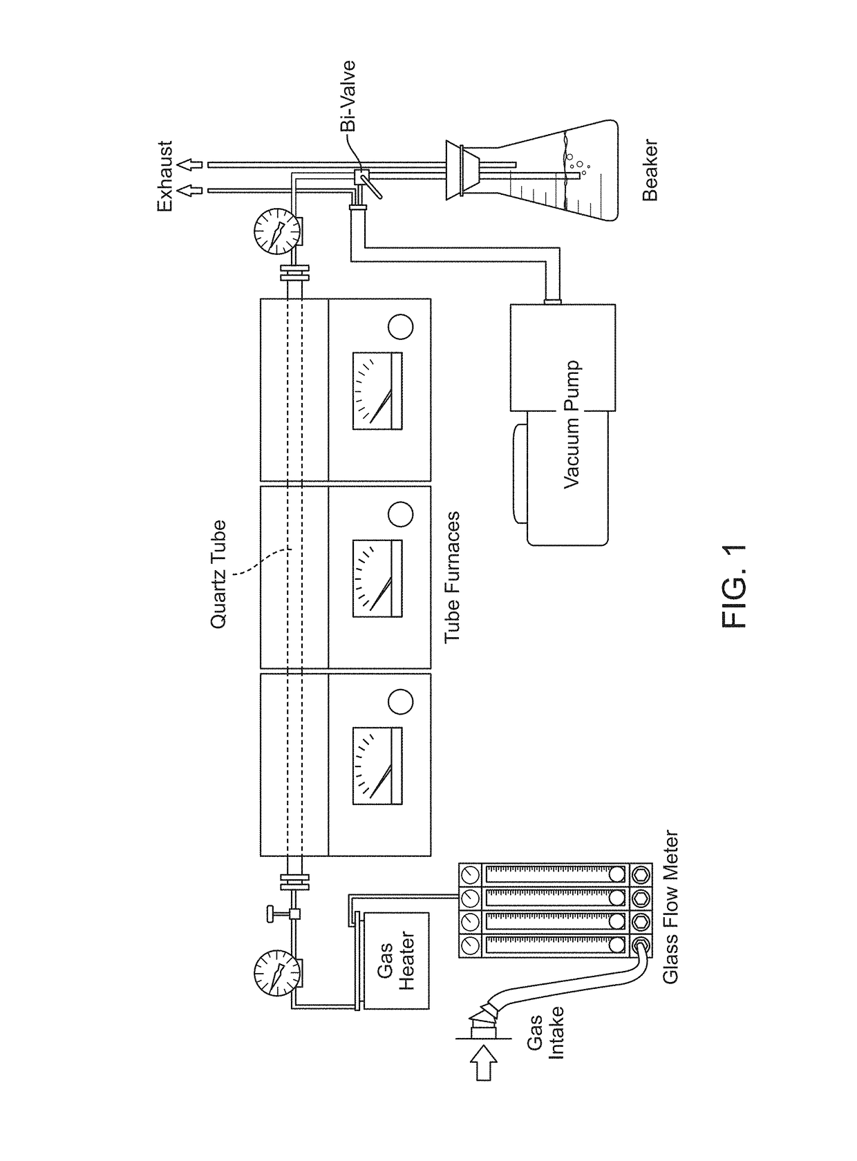
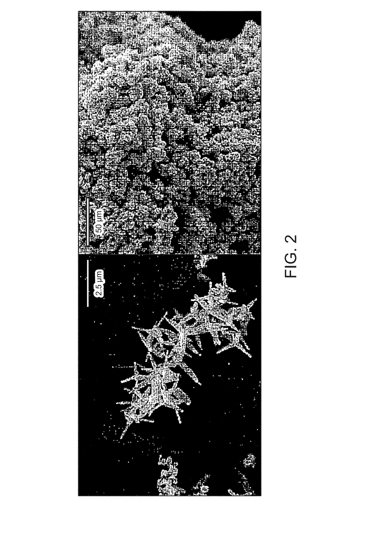
[0062]An experimental set-up for synthesizing zinc oxide tetrapods or agglomerates is shown as FIG. 1. A batch of either zinc oxide tetrapods (ZnO-T) or agglomerates (ZnO-A) was synthesized by the vapor transport method and sol-gel process, respectively (FIG. 2).

[0063]For the process of the vapor-transport method, a boat with pure zinc powder was placed in a horizontal tube furnace with the atmosphere purged and replaced with a mixture of oxygen and argon. The zinc vapor flowed down the quartz tube and condensed on a cooler surface such as silicon wafer and nucleates into tetrapods (FIG. 2).

[0064]For the sol-gel process, a mixture of zinc acetate, citric acid, and water were placed into a boat, which was then placed into a tube furnace in a pure oxygen atmosphere. The heat from the furnace forced the mixture to combust and incinerate into zinc oxide agglomerates (FIG. 2). A prospective view of a solar cell utilizing a composition of the present...

example 2

of Zinc Oxide Agglomerates

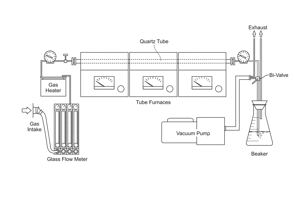
[0072]The synthesis of the zinc oxide tetrapods (ZnO-T) and zinc oxide agglomerates (ZnO-A) were carried out in a makeshift tube furnace made from three different tube furnaces with an intake gas flow meter, preheater, vacuum pump, and a beaker to collect any airborne particulates (FIG. 1).

[0073]The zinc oxide agglomerates can be made by mixing zinc salts in the appropriate stoichiometric amounts with citric acid and deionized water (1:5 molar ratio of mixture to water, respectfully). The zinc salts that were and can be used are: zinc acetate dihydrate, zinc chloride, zinc monohydrate, zinc nitrate hexahydrate. When mixed, the compound is stirred on a hot plate until everything is dissolved and heated at around 80° C. for approximately five minutes. Then the compound will begin to gel upon cooling when this occurs it is poured into a crucible, which is then placed into a tube furnace with temperature and atmospheric controls with a quartz tube. The atmosphe...

example 3

of Zinc Oxide Tetrapods

[0074]The two primary methods for synthesizing ZnO tetrapods are the chemical vapor transport method and the vapor transport method. For the chemical vapor transport method, the process begins with a 5:1 weight ratio of zinc carbonate powder (ZnCO3*2Zn(OH)2*H2O) to graphite powder (particle size range approximately 20 micrometers). The sample is placed in a crucible within a quartz tube which is then placed in a tube furnace with a silicon wafer positioned either transversal downstream or parallel above the crucible, with respect to the tube furnace. The tube furnace is set to 900° C. with the atmosphere purged and replaced with 0.5-5% oxygen mixed with an inert gas such as nitrogen or argon, with a flow rate of approximately 500 sccm. The temperature is held at 900° C. for about ten minutes, and after sufficient cooling it removed and the ZnO tetrapods are collected from the wafer.

[0075]The vapor transport method. This method uses pure zinc powder (5-300 mic...


PUM

PropertyMeasurementUnit
sizeaaaaaaaaaa
particle sizeaaaaaaaaaa

Abstract

A composition for covering satellite solar panels includes an encapsulating resin, a conductive nano-network, and fused silica / quartz beads. A coverglass for a satellite solar panel includes such a composition. A method for producing the composition includes the steps of mixing an encapsulating resin, a conductive nano-network, and fused silica / quartz beads at a specific ratio, so that the ratio maximizes the inherent properties; and tape casting the mixture to create the composition.

Description

CROSS REFERENCE TO RELATED APPLICATIONS[0001]This application claims the benefit of U.S. Provisional Application No. 62 / 357,197, filed Jun. 30, 2016, which is incorporated herein by reference in its entirety.TECHNICAL FIELD[0002]The subject matter disclosed herein is generally directed to solar cell semiconductor devices. Specifically, the present disclosure is related to a cover glass replacement for modern composites used on satellite solar panels to provide protection from radiation, oxygen bombardment, and debris.BACKGROUND[0003]The present invention relates generally to solar cell semiconductor devices, and particularly to the composition and structure of cover glass replacements for satellite solar panels.[0004]Standard space solar arrays generally consist of a plurality of solar cells that are adhered in some manner to substantially rigid patent substrates and then covered with glass microsheets. The combination of the substrates and in particular the glass microsheets provid...

Claims


Application Information

Patent Timeline
Patent Type & Authority Applications(United States)
IPC IPC(8): H01L31/048C08K3/22C08K7/20C03C12/00H01L31/054C08K5/092H01L31/02C01G9/03
CPCH01L31/0481C08K2201/005C01G9/03C08K7/20C08K3/22C08K5/092H01L31/02008H01L31/054C01P2004/30C01P2004/50C01P2006/40C01P2002/60C08K2003/2296C08K2201/001C03C12/00C01G9/02C01P2002/84C01P2004/03C01P2004/64C03C17/008C03C17/009C03C2217/445C03C2217/475C08K3/40C08K2201/014Y02E10/52
Inventor CLIFT, PHILLIPWLADYKA, JORDANPAYTON, TYLER
Owner CELEVATOR PHILLIP
Learn More