Combined additive manufacturing method applicable to parts and molds

Active Publication Date: 2019-10-31
HUAZHONG UNIV OF SCI & TECH
View PDF0 Cites 1 Cited by
  • Summary
  • Abstract
  • Description
  • Claims
  • Application Information

AI Technical Summary

Benefits of technology

[0027]The present invention maintains the high-speed cold spraying as a “cold processing” of low heat input, which can effectively avoid the thermal-induced adverse effects occurring during the “hot forming process” of thermal spraying and deposition of laser, electron beam, arc and the like. The present invention can obtain parts or molds of metals, intermetallic compounds, cermets, ceramics and composite gradient functional materials with high quality, fastness and low cost.
[0028]The method of the present invention solves the practical engineering problem, and the parts or molds prepared by the method of the present invention have no thermal defects such as pores, shrinkage, unfusion, slag inclusion, dilution, oxidation, decomposition

Problems solved by technology
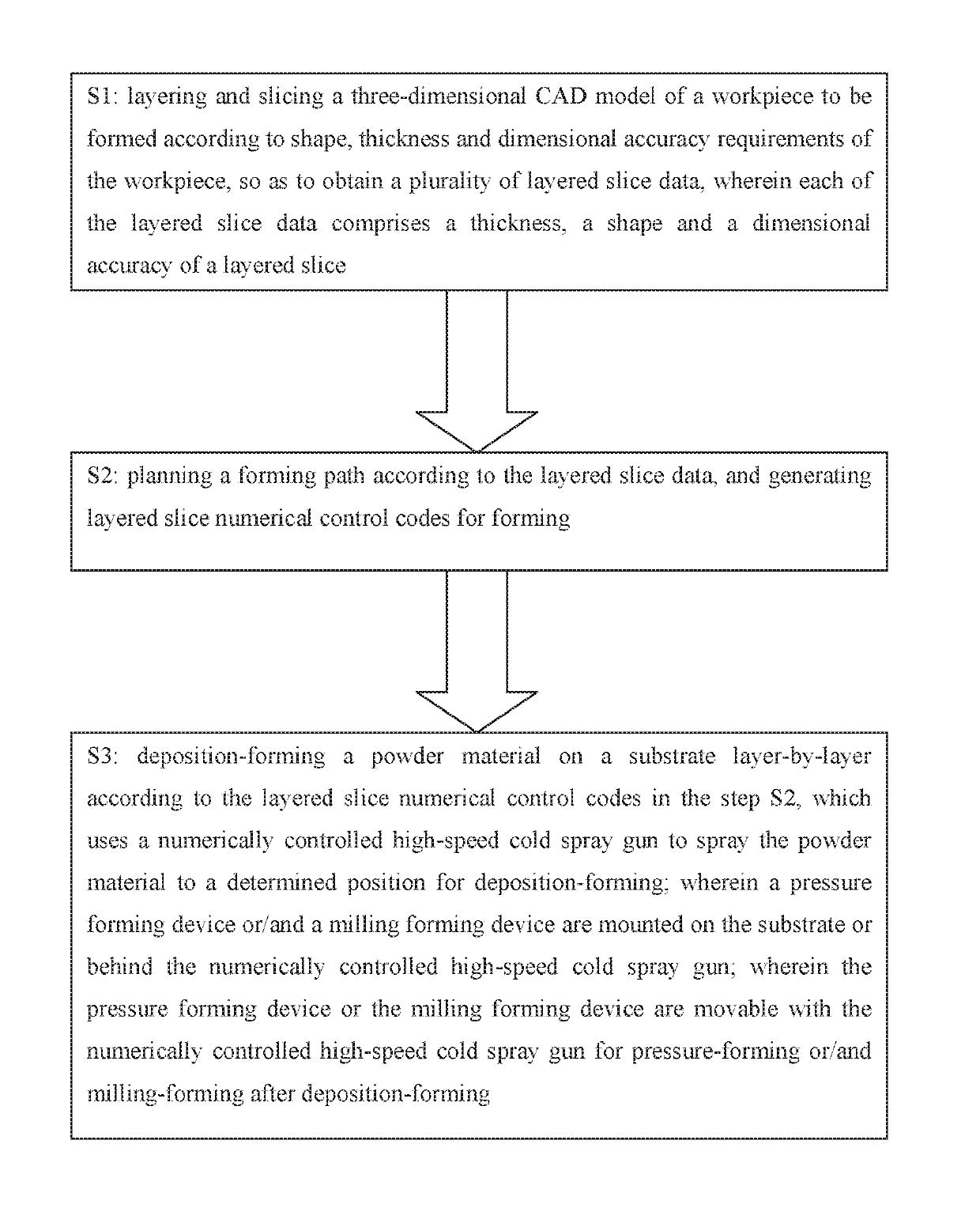
The method has high forming precision and density of the workpiece is much higher than that of selective laser sintered parts, but the forming efficiency, and energy and material utilization are not high.
It is difficult to reach full density while equipment investment and operating costs are high (see: A. J. Pinkkerton, L. Li, Effects of Geometry and Composition in Coaxial Laser Deposition of 316L Steel for Rapid Protyping, Annals of the CIRP, Vol. 52, 1(2003), p 181-184).
The method has high forming precision and good forming quality, but the process conditions are strict, wherein the entire forming process needs to be carried out in a vacuum, resulting in limited forming dimensions, high equipment investment and high operating costs.
Furthermore, it is difficult to be used for forming gradient functional material parts due to the same layering method as selective sintering (see: Matz J. E., Eagar T. W. Carbide formation in Alloy 718 during electron-beam solid freeform fabrication.
However, because the diameter of the arc column is larger than that of the former two, the size and surface precision of the forming are not as good as the former two.
However, the directly formed difficult-to-machine material parts increase the surface hardness due to rapid solidification, which makes processing very difficult.
Parts with complicated shapes need to be clamped many times, resulting in long processing time, sometimes even accounting for more than 60% of the entire manufacturing cycle.
It has become a bottleneck for low-cost short-flow growth manufacturing of high-performance and difficult-to-machine parts.
At the same time, due to being unsupported, during the forming

Method used


Image

  • Combined additive manufacturing method applicable to parts and molds

Examples


Example

Embodiment 1

[0038]According to performance requirements of iron-nickel-chromium alloy parts, high-speed cold spray forming is carried out using iron-nickel-chromium alloy powder.

[0039]On a substrate, according to a digital additive forming path obtained by a three-dimensional CAD model of a part, a high-speed cold spray gun is used to move above the substrate to be formed to perform metal deposition forming;

[0040]wherein during the forming process, a micro roll fixed behind the high-speed cold spray gun moves therewith, so high-speed cold spray forming and continuous cold forging rolling pressure forming are simultaneously performed; if dimension and surface precision cannot satisfy requirements, surface finishing is needed during the above synchronous forming process layer-by-layer or layers-by-layers. Therefore, according to grinding and polishing path planning combined with the synchronous forming process path, grinding and polishing are performed layer-by-layer or layers-by-laye...

Example

Embodiment 2

[0042]According to performance requirements of high-temperature alloy parts, high-speed cold spray forming is carried out using high-temperature alloy powder.

[0043]On a substrate, according to a digital additive forming path obtained by a three-dimensional CAD model of a part, a high-speed cold spray gun is used to move above the substrate to be formed to perform metal deposition forming;

[0044]wherein during the forming process, a spin forming device fixed behind the high-speed cold spray gun moves therewith, so high-speed cold spray forming and rotary pressure forming are simultaneously performed; if dimension and surface precision cannot satisfy requirements, surface finishing is needed during the above synchronous forming process layer-by-layer or layers-by-layers. Therefore, according to grinding and polishing path planning combined with the synchronous forming process path, grinding and polishing are performed layer-by-layer or layers-by-layers during the synchronou...

Example

Embodiment 3

[0046]According to performance requirements of aluminium alloy parts, high-speed cold spray forming is carried out using aluminium alloy powder.

[0047]On a substrate, according to a digital additive forming path obtained by a three-dimensional CAD model of a part, a high-speed cold spray gun is used to move above the substrate to be formed to perform metal deposition forming;

[0048]wherein during the forming process, a milling cutter, laser or electric spark milling machine fixed behind the high-speed cold spray gun moves therewith, so high-speed cold spray forming and milling forming are simultaneously performed; if dimension and surface precision cannot satisfy requirements, surface finishing is needed during the above synchronous forming process layer-by-layer or layers-by-layers. Therefore, according to grinding and polishing path planning combined with the synchronous forming process path, grinding and polishing are performed layer-by-layer or layers-by-layers during ...


PUM


Abstract

A combined additive manufacturing method applicable to parts and molds relates to moldless-growth manufacturing of parts and molds, which includes steps of: S1: layering and slicing a three-dimensional CAD (computer-aided design) model of a workpiece to be formed according to shape, thickness and dimensional accuracy requirements of the workpiece, so as to obtain a plurality of layered slice data; S2: planning a forming path according to the layered slice data, and generating layered slice numerical control codes for forming; and S3: deposition-forming a powder material on a substrate layer-by-layer and performing pressure forming or milling forming according to the layered slice numerical control codes in the step S2, which uses a numerically controlled high-speed cold spray gun to spray the powder material to a determined position for deposition-forming. The method of the present invention overcomes thermally induced adverse effects of hot processing and drawbacks of cold spray deposition.

Description

CROSS REFERENCE OF RELATED APPLICATION[0001]This is a U.S. National Stage under 35 U.S.C 371 of the International Application PCT / CN2017 / 112908, filed Nov. 24, 2017, which claims priority under 35 U.S.C. 119(a-d) to CN 201611034046.0, filed Nov. 18, 2016.BACKGROUND OF THE PRESENT INVENTIONField of Invention[0002]The present invention relates to moldless-growth manufacturing of parts and molds, and more particularly to a combined additive manufacturing method applicable to parts and molds.Description of Related Arts[0003]The moldless deposition forming method of high-density metal parts or molds mainly includes high-power laser deposition forming, electron beam free forming, plasma arc and arc deposition forming.[0004]Among them, the high-power laser deposition forming adopts a high-power laser to melt the metal powder sent to the substrate layer by layer, and rapidly solidify for deposition forming, thereby finally obtaining a near-finished part. The method has high forming precisio...

Claims


Application Information

Patent Timeline
IPC IPC(8): B24B19/22B33Y10/00B22F10/10B22F10/66
CPCB22F2003/242B22F2003/1058B22F3/1055B24B19/22B33Y10/00B28B1/32Y02P10/25B33Y50/02B33Y40/20B22F10/50B22F2999/00C23C24/04B22F10/25B22F10/20B22F2207/01B22F2201/02B22F2003/247B22F3/18B29C44/367
Inventor ZHANG, HAIOUWANG, GUILANZHANG, HUAYU
Owner HUAZHONG UNIV OF SCI & TECH
Why Eureka
Try Eureka