
Method for directly producing ethanol from syngas

a technology of syngas and ethanol, which is applied in the field of converting syngas into ethanol, can solve the problems of difficult large-scale development, limited biosynthetic fuel ethanol, and operating costs, and achieve the effects of reducing equipment investment costs, reducing energy consumption, and reducing methanol synthesis

Inactive Publication Date: 2020-07-23
DALIAN INST OF CHEM PHYSICS CHINESE ACAD OF SCI
View PDF0 Cites 2 Cited by
  • Summary
  • Abstract
  • Description
  • Claims
  • Application Information

AI Technical Summary

Benefits of technology

The present invention provides a new way to convert syngas into ethanol. This method reduces the need for methanol synthesis and separation, resulting in lower equipment investment and energy consumption. The process is simple and can be applied to a range of applications. Overall, this invention offers a more efficient and cost-effective way to produce ethanol.

Problems solved by technology

However, biosynthetic fuel ethanol is limited by the characteristics of the shortage of raw materials and low energy density, which makes it difficult to develop on a large scale.
From the point of view of process and cost, the process of direct preparation of ethanol from syngas is short, the operating cost is relatively economical, and the investment cost is low.
However, from the perspective of thermodynamics and kinetics, it is difficult for the reaction to stay on the target product, i.e. ethanol.
Because the direct preparation of ethanol from syngas is a strong exothermic reaction, the first problem is to choose a catalyst with good catalytic performance, high selectivity and strong resistance.
The selectivity of ethanol is not ideal and the yield is low.
However, the use of precious metal such as rhodium has greatly increased the production cost of ethanol, and the production of rhodium is limited.
There is great difficulty in large-scale promotion and application, which has become the bottleneck of the industrialization of this process route.
Significantly reducing the use of rhodium or replacing rhodium with non-precious metal catalysts is an effective way to promote the industrialization of this technology, but progress is currently relatively slow.

Method used


Image

  • Method for directly producing ethanol from syngas
  • Method for directly producing ethanol from syngas

Examples


example 1

[0053]Catalyst 11# was used in the first reaction zone, catalyst B (copper-based catalyst) was used in the second reaction zone, and catalyst C was used in the third reaction zone.

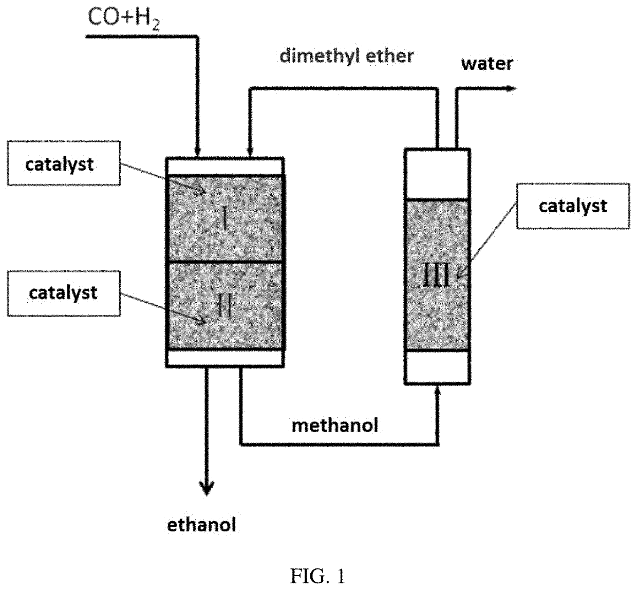
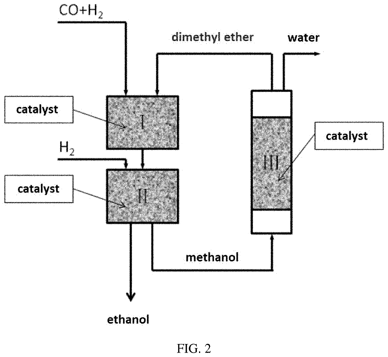
[0054]In the fixed-bed reactor, syngas containing CO and H2 together with dimethyl ether (DME) passed through the first reaction zone and the second reaction zone. The first reaction zone and the second reaction zone were located in the same reactor, wherein the whole of part of dimethyl ether was produced from methanol generated from CO and H2 in the second reaction zone through the dehydration reaction in the third reaction zone. The specific reaction scheme was shown in FIG. 1, wherein the syngas and dimethyl ether as raw materials were allowed to enter the first reaction zone I to contact with the solid acid catalyst 11# in the first reaction zone and react to obtain an effluent containing methyl acetate and / or acetic acid; the effluent from the first reaction zone was allowed to enter the second react...

example 2

[0057]Different catalysts (1-10# and 12-16#, see Table 4) were used in the first reaction zone, catalyst B was used in the second reaction zone, and catalyst C was used in the third reaction zone.

[0058]In the fixed-bed reactor, syngas containing CO and H2 together with dimethyl ether (DME) passed through the first reaction zone and the second reaction zone. The first reaction zone and the second reaction zone were located in the same reactor (the specific reaction process was shown in FIG. 1 and Example 1), wherein dimethyl ether was produced from methanol generated from CO and H2 in the second reaction zone through the dehydration reaction in the third reaction zone. The reaction conditions were as follows: different catalysts (1-10# and 12-16#, see Table 4) and catalyst B were charged into the first reaction zone and the second reaction zone of the reactor from top to bottom, respectively, and 3 g and 7 g were charged respectively. The molar ratio of CO, DME and H2 was 2:1:12. The...

example 3

[0059]Similar to the procedure of Example 1, in the fixed-bed reactor, the reaction temperature was 215° C., and the reaction pressures were 1, 8 and 15 MPa, respectively. The other reaction conditions were the same as in Example 1. The reaction results when the mixed gas containing CO and H2 together with dimethyl ether passed through the first reaction zone and the second reaction zone were shown in Table 5.

TABLE 5Reaction results at different reaction pressuresPercentPercentSelectivitySelectivityconversion ofconversion ofSelectivitySelectivityfor methylfor ethylSelectivityReactiondimethyl ethercarbon monoxidefor methanolfor ethanolacetateacetatefor otherspressure / MPa(%)(%)(%)(%)(%)(%)(%)117.811.2547.8938.974.188.940.02837.522.2645.2354.770.000.000.001545.025.8244.3956.610.000.000.00


PUM

PropertyMeasurementUnit
volume ratioaaaaaaaaaa
pressureaaaaaaaaaa
temperatureaaaaaaaaaa

Abstract

A method for directly producing ethanol from syngas, carried out in three reaction zones, including: feeding a raw material containing syngas and dimethyl ether into a first reaction zone to contact with a solid acid catalyst, reacting; allowing the effluent from the first reaction zone to enter a second reaction zone to contact with a metal catalyst and react; separating the effluent from the second reaction zone to obtain product ethanol and by-product methanol; allowing by-product methanol to enter a third reaction zone to perform a dehydration reaction to obtain dimethyl ether, and allowing the obtained dimethyl ether to enter the first reaction zone to recycle the reaction. This provides a novel method for directly converting syngas to ethanol and an ethanol product can be directly produced by using syngas as a raw material.

Description

TECHNICAL FIELD[0001]The present invention relates to a method for converting syngas into ethanol.BACKGROUND[0002]Ethanol is recognized as an environmentally friendly clean fuel in the world. It can be used directly as a liquid fuel or mixed with gasoline to reduce the emissions of carbon monoxide, hydrocarbons, particulate matter, nitrogen oxides and benzene-based harmful to substances in automobile exhaust, which can effectively improve China's Environmental quality is of great significance for solving China's air pollution problems and achieving sustainable development. Existing ethanol production processes mainly include a sugar or cellulose fermentation method based on a biomass route and an ethylene hydration method based on a petroleum route. In recent years, China's fuel ethanol production and sales have grown rapidly, and it has become the world's third largest fuel ethanol producer after the United States and Brazil. However, biosynthetic fuel ethanol is limited by the cha...

Claims


Application Information

Patent Timeline
Patent Type & Authority Applications(United States)
IPC IPC(8): C07C29/154B01J19/18
CPCC07C31/08B01J19/1818C07C29/154C07C29/149C07C29/151Y02P20/52C07C67/37C07C51/12C07C29/095C07C41/09C07C69/14C07C53/08C07C31/04C07C43/043C07C29/153
Inventor LIU, HONGCHAOZHU, WENLIANGLIU, ZHONGMINLIU, YONGLIU, SHIPINGWEN, FULINI, YOUMINGMA, XIANGANG
Owner DALIAN INST OF CHEM PHYSICS CHINESE ACAD OF SCI
Learn More