Eureka AIR delivers breakthrough ideas for toughest innovation challenges, trusted by R&D personnel around the world.

Method of producing graphene-carbon hybrid foam-protected anode active material coating for lithium-ion batteries

Pending Publication Date: 2020-07-23
GLOBAL GRAPHENE GRP INC
View PDF3 Cites 1 Cited by
  • Summary
  • Abstract
  • Description
  • Claims
  • Application Information

AI Technical Summary

Benefits of technology

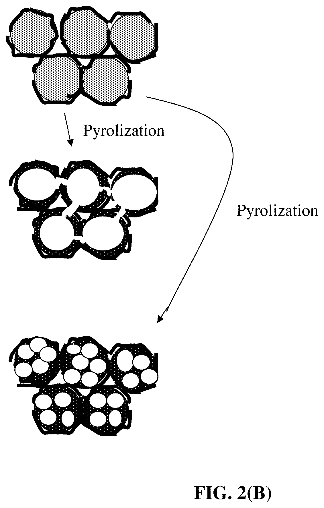
The patent describes a method for producing a 3D graphene-carbon hybrid foam, which is a simple and efficient process. The foam is made by heating a mixture of graphite particles and polymer particles at high temperatures, which results in the formation of a carbon material that bridges the gaps between the graphene sheets. This carbon material acts as a continuous network of electron-conducting pathways, allowing for the continuous transport of electrons and phonons between the graphene sheets. The resulting foam has both high electric and thermal conductivity. The technical effect of this method is the production of a highly conductive and thermally efficient foam material.

Problems solved by technology

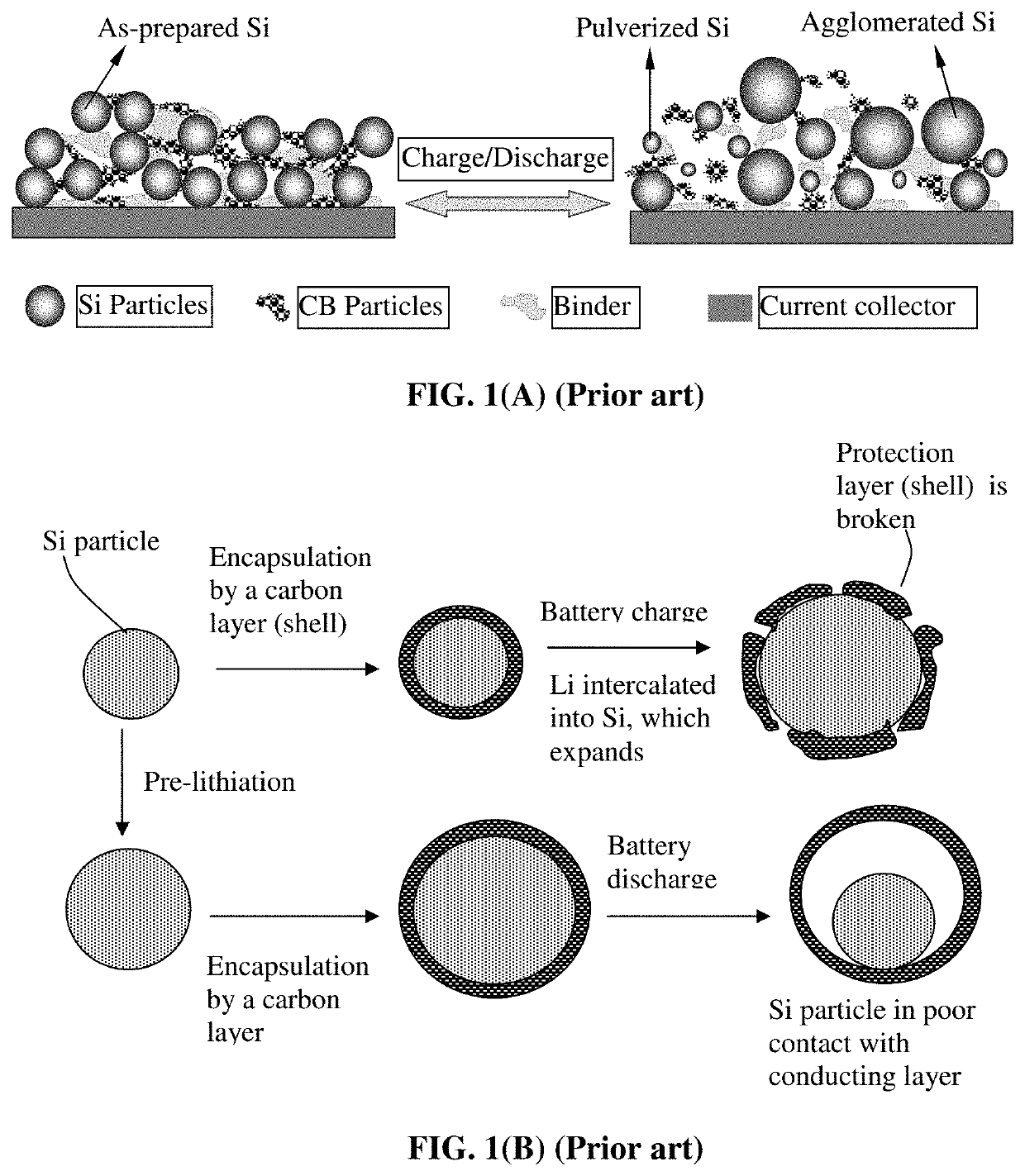
However, as schematically illustrated in FIG. 2(A), in an anode composed of these high-capacity materials, severe pulverization (fragmentation of the alloy particles) occurs during the charge and discharge cycles due to severe expansion and contraction of the anode active material particles induced by the insertion and extraction of the lithium ions in and out of these particles.
The expansion and contraction, and the resulting pulverization, of active material particles, lead to loss of contacts between active material particles and conductive additives and loss of contacts between the anode active material and its current collector.
These adverse effects result in a significantly shortened charge-discharge cycle life.
Such a reaction is undesirable since it is a source of irreversible capacity loss.(2) depositing the electrode active material in a thin film form directly onto a current collector, such as a copper foil.
However, such a thin film structure with an extremely small thickness-direction dimension (typically much smaller than 500 nm, often necessarily thinner than 100 nm) implies that only a small amount of active material can be incorporated in an electrode (given the same electrode or current collector surface area), providing a low total lithium storage capacity and low lithium storage capacity per unit electrode surface area (even though the capacity per unit mass can be large).
Such a thin-film battery has very limited scope of application.
Unfortunately, when an active material particle, such as Si particle, expands (e.g. up to a volume expansion of 380%) during the battery charge step, the protective coating is easily broken due to the mechanical weakness and / o brittleness of the protective coating materials.
There has been no high-strength and high-toughness material available that is itself also lithium ion conductive.
These protective materials are all very brittle, weak (of low strength), and / or non-conductive to lithium ions (e.g., ceramic or oxide coating).
(d) The protective material must not provide any significant amount of defect sites that irreversibly trap lithium ions.
The prior art protective materials all fall short of these requirements.
Furthermore, in most cases, the electrode was not capable of operating for a large number of cycles.
Additionally, most of these electrodes are not high-rate capable, exhibiting unacceptably low capacity at a high discharge rate.
Due to these and other reasons, most of prior art composite electrodes and electrode active materials have deficiencies in some ways, e.g., in most cases, less than satisfactory reversible capacity, poor cycling stability, high irreversible capacity, ineffectiveness in reducing the internal stress or strain during the lithium ion insertion and extraction steps, and other undesirable side effects.
In summary, the prior art has not demonstrated a material that has all or most of the properties desired for use as an anode active material in a lithium-ion battery.

Method used


Image

  • Method of producing graphene-carbon hybrid foam-protected anode active material coating for lithium-ion batteries
  • Method of producing graphene-carbon hybrid foam-protected anode active material coating for lithium-ion batteries
  • Method of producing graphene-carbon hybrid foam-protected anode active material coating for lithium-ion batteries

Examples


example 1

n of Graphene-Carbon Foam from Flake Graphite Via Polypropylene Powder-Based Solid Polymer Carrier

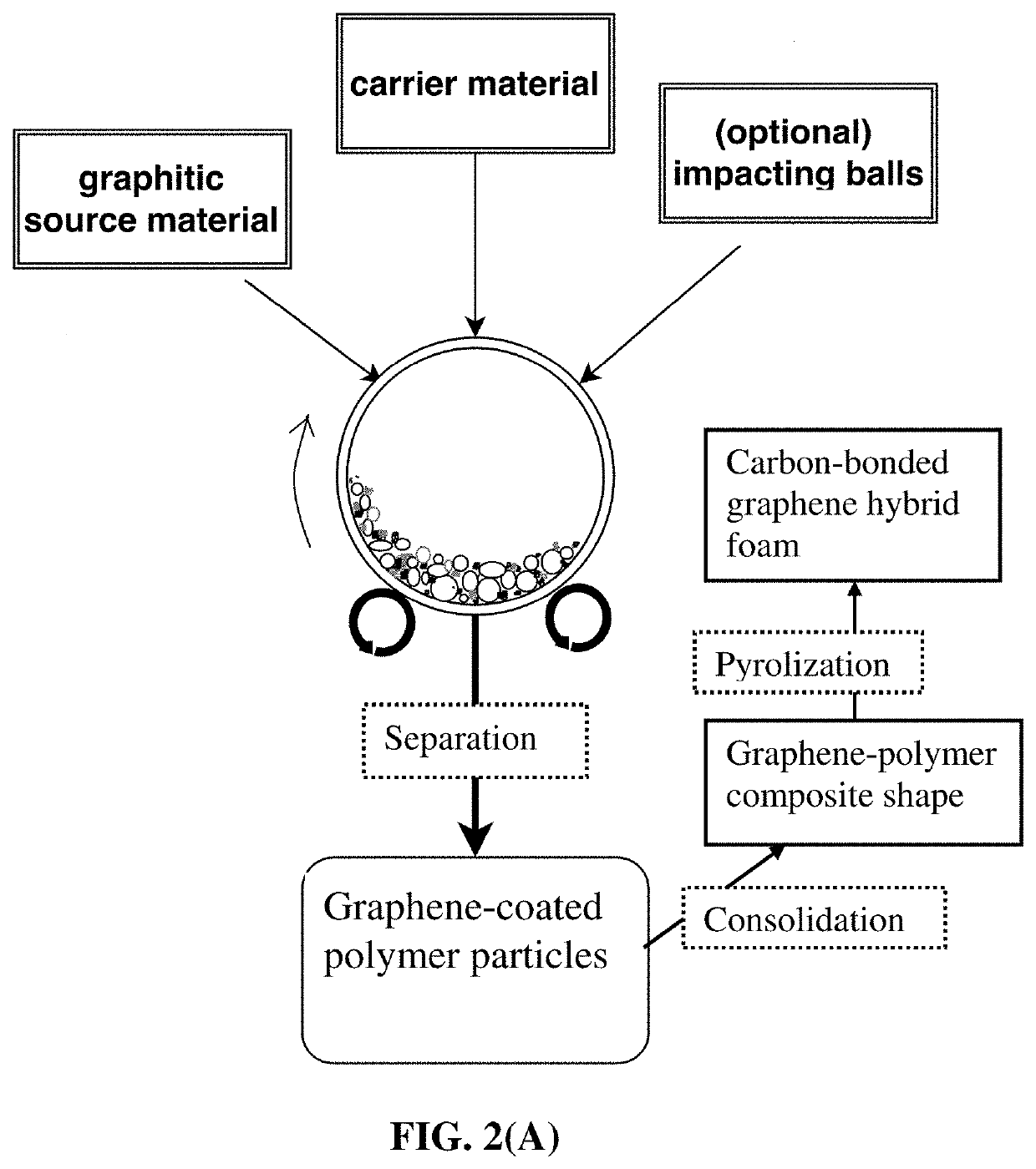
[0120]In an experiment, 1 kg of polypropylene (PP) pellets, 50 grams of flake graphite, 50 mesh (average particle size 0.18 mm; Asbury Carbons, Asbury N.J.) and 250 grams of magnetic steel balls were placed in a high-energy ball mill container. The ball mill was operated at 300 rpm for 2 hours. The container lid was removed and stainless steel balls were removed via a magnet. The polymer carrier material was found to be coated with a dark graphene layer. Carrier material was placed over a 50 mesh sieve and a small amount of unprocessed flake graphite was removed.

[0121]A sample of the coated carrier material was then immersed in tetrachloroethylene at 80° C. for 24 hours to dissolve PP and allow graphene sheets to disperse in the organic solvent. After solvent removal, isolated graphene sheet powder was recovered (mostly few-layer graphene). The remaining coated carrier material was then...

example 2

Carbon Hybrid Foam Using Expanded Graphite (>100 nm in Thickness) as the Graphene Source and ABS as the Polymer Solid Carrier Particles

[0125]In an experiment, 100 grams of ABS pellets, as solid carrier material particles, were placed in a 16 oz plastic container along with 5 grams of expanded graphite. This container was placed in an acoustic mixing unit (Resodyn Acoustic mixer) and processed for 30 minutes. After processing, carrier material was found to be coated with a thin layer of carbon. A small sample of carrier material was placed in acetone and subjected to ultrasound energy to speed dissolution of the ABS. The solution was filtered using an appropriate filter and washed four times with additional acetone. Subsequent to washing, filtrate was dried in a vacuum oven set at 60° C. for 2 hours. This sample was examined by optical microscopy and found to be graphene. The remaining pellets were extruded to create graphene-polymer sheets (1 mm thick), which were then carbonized to...

example 3

n of Graphene-Carbon Hybrid Foam from Mesocarbon Microbeads (MCMBs as the Graphene Source Material) and Polyacrylonitrile (PAN) Fibers (as Solid Carrier Particles)

[0126]In one example, 100 grams of PAN fiber segments (2 mm long as the carrier particles), 5 grams of MCMBs (China Steel Chemical Co., Taiwan), and 50 grams of zirconia beads were placed in a vibratory ball mill and processed for 2 hours. After the process was completed, the vibratory mill was then opened and the carrier material was found to be coated with a dark coating of graphene sheets. The zirconia particles, having distinctly different sizes and colors were manually removed. The graphene-coated PAN fibers were then compacted and melted together to form several composite films. The films were subjected to a heat treatment at 250° C. for 1 hour (in room air), 350° C. for 2 hours, and 1,000° C. for 2 hours (under an argon gas atmosphere) to obtain graphene-carbon foam layers. Half of the carbonized foam layers were th...


PUM


Abstract

Provided is method of producing a porous anode material structure for a lithium-ion battery, the method comprising (A) providing an integral 3D graphene-carbon hybrid foam comprising multiple pores, having a pore volume Vp, and pore walls; and (B) impregnating or infiltrating the pores with a fluid for forming a coating of an anode active material, having a coating volume Vc, deposited on or bonded to surfaces of the pore walls; wherein the pore walls contain single-layer or few-layer graphene sheets chemically bonded by a carbon material having a carbon material-to-graphene weight ratio from 1 / 200 to 1 / 2, and wherein the volume ratio Vp / Vc is from 0.1 / 1.0 to 10 / 1.0.

Description

FIELD OF THE INVENTION[0001]The present invention relates generally to the field of lithium batteries and, in particular, to an environmentally benign and cost-effective method of producing graphene / carbon hybrid foam-supported anode active material coatings for lithium-ion batteries.BACKGROUND OF THE INVENTION[0002]A unit cell or building block of a lithium-ion battery is typically composed of an anode current collector, an anode or negative electrode layer (containing an anode active material responsible for storing lithium therein, a conductive additive, and a resin binder), an electrolyte and porous separator, a cathode or positive electrode layer (containing a cathode active material responsible for storing lithium therein, a conductive additive, and a resin binder), and a separate cathode current collector. The electrolyte is in ionic contact with both the anode active material and the cathode active material. A porous separator is not required if the electrolyte is a solid-st...

Claims


Application Information

Patent Timeline
IPC IPC(8): H01M4/587H01M10/0525
CPCH01M4/587H01M2004/021H01M10/0525H01M2004/027Y02E60/10H01M4/625H01M4/366
Inventor JANG, BOR Z.
Owner GLOBAL GRAPHENE GRP INC
Why Eureka
Eureka Blog
Learn More