
Fluorescent systems for biological imaging and uses thereof

a biological imaging and fluorescent system technology, applied in the field of fluorescence compounds, can solve the problems of difficult development of reliable markers for non-mammalian cell types, limited use of fluorescent probes and therapeutics, and poor signal quality and specificity

Pending Publication Date: 2022-11-03
LIGHTOX LTD
View PDF0 Cites 0 Cited by
  • Summary
  • Abstract
  • Description
  • Claims
  • Application Information

AI Technical Summary

Benefits of technology

The patent text describes a new compound that can be used in biological imaging techniques. This compound has the advantage of being a versatile fluorescent probe that can be attached to different targeting molecules or reactive groups. It can also be used to generate reactive oxygen species, which can control cellular development and has therapeutic applications. The compound has good physical properties, such as solubility, and can be used in a variety of imaging techniques. Overall, this compound provides a useful tool for studying biological processes and has potential applications in biological imaging and drug development.

Problems solved by technology

However, the expansive biology of retinoid signalling makes targeting using retinoids difficult, thereby limiting their broader use as fluorescent probes and as therapeutics.
The development of reliable markers for non-mammalian cell types is also challenging.
For instance, although some commercially available fluorescent probes that target specific organelle in mammalian cells can be used in plants, signal quality and specificity are often poor, and labelling efficiency is impacted by the relatively high molecular weight of the fluorescent compounds.
In addition, known fluorescent probes often have an excitation range similar to chlorophyll, leading to signal interference in plant cell imaging.

Method used


Image

  • Fluorescent systems for biological imaging and uses thereof
  • Fluorescent systems for biological imaging and uses thereof
  • Fluorescent systems for biological imaging and uses thereof

Examples


example 1

OF EXEMPLARY COMPOUNDS OF FORMULA I

1.1 Synthesis of Coupling Partners

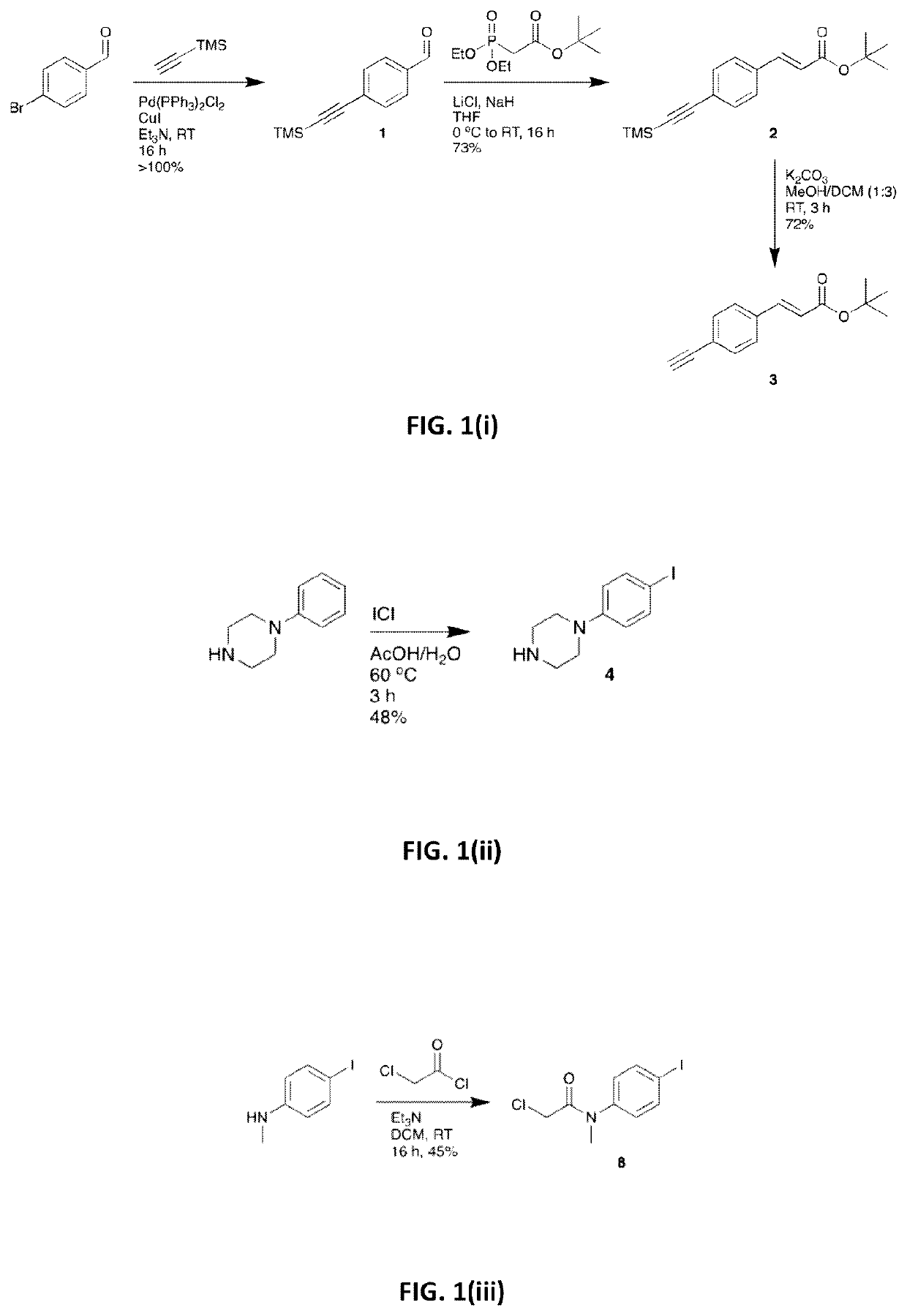
1.1.1. Synthesis of tert-butyl (2E)-3-(4-ethynylphenyl)prop-2-enoate, 3

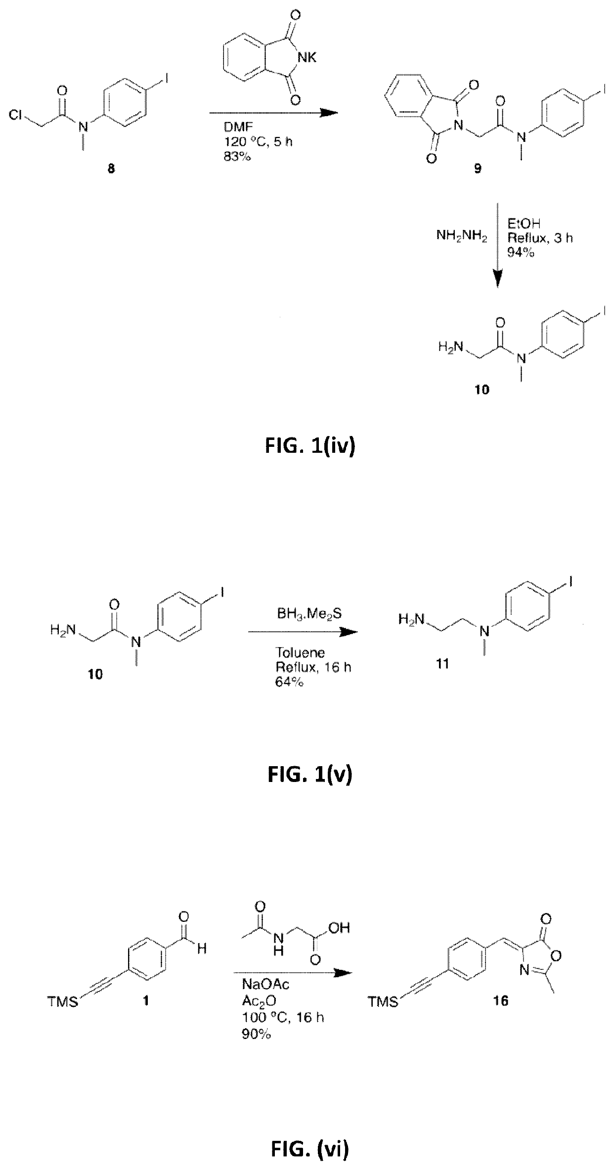
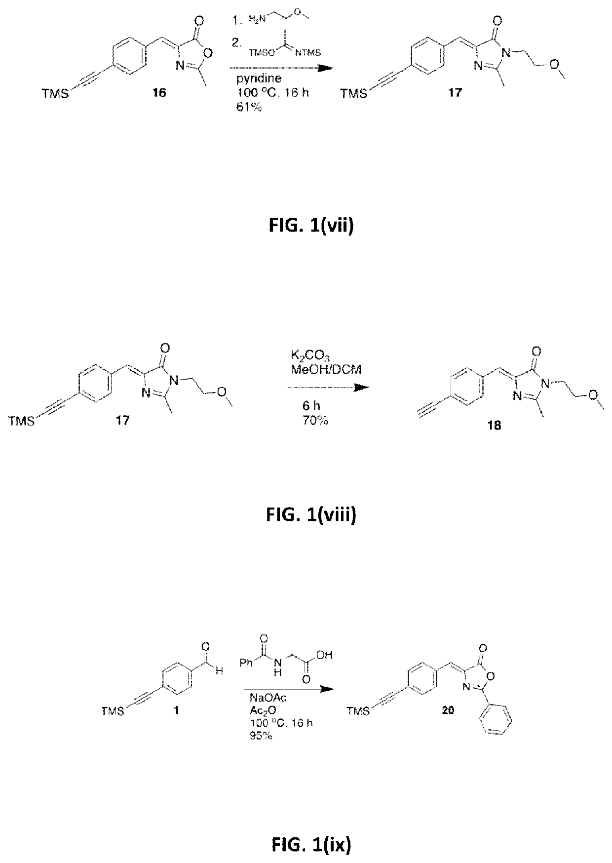
[0153]The synthesis of tert-butyl (2E)-3-(4-ethynylphenyl)prop-2-enoate (3) is illustrated in FIG. 1(i). Triethylamine (Et3N) (250 mL) was degassed by sparging with Ar for 1 hour. 4-Bromobenzaldehyde (18.5 g, 100.0 mmol), Pd(PPh3)2Cl2 (1.4 g, 2.00 mmol), Cul (0.38 g, 2.00 mmol) and trimethylsilylacetylene (15.2 mL, 110.0 mmol) were then added under Ar and the resultant suspension was stirred at room temperature (RT) for 16 hours (h). The suspension was diluted with heptane, passed through a short Celite / SiO2 plug and the extracts were evaporated to give a crude dark solid (24 g). This was purified by Kugelrohr distillation (130-150° C., 9.0 Torr) to give compound 1 as an off-white solid (21.5 g, >100%), which was carried to the next step without further purification. Tert-butyl diethylphosphonoacetate (14.4 mL, 61.5 mmol) and LiCl (2.54 g, 60.0 ...

example 2

NT OF ABSORPTION AND FLUORESCENCE EMISSION OF EXEMPLIFIED COMPOUNDS

[0228]Peak absorption and fluorescence emission wavelengths of compounds 6, 7, 12, 13, 14, 15, 19, 23, 27, 30 and 34 were measured in a variety of solvents, and the results are shown in Table 1. Absorption measurements were recorded at a concentration of 10 μM, and emission measurements were recorded at a concentration of 100 nM. Emission spectra were recorded with excitation at the peak of absorption (S0→S1).

TABLE 1Peak absorption and emission wavelengths of compounds 6, 7, 12, 13, 14, 15, 19, 23, 27, 30 and 34 in a variety of solvents.CompoundSolventλabs(max) / nmλem(max) / nm6Toluene358482DCM3685507Toluene361504DCM36256312Toluene380482DCM37155113Toluene358464DCM36154714Toluene367506DCM36153115Toluene381473DCM37754519Toluene403515Chloroform403584MeOH395—23Chloroform42461627Toluene380493DCM37152430Chloroform37453534Chloroform432628

example 3

ICAL COMPARISON OF PARA-SUBSTITUTED AND ORTHO-SUBSTITUTED COMPOUNDS

[0229]To compare the photophysical behaviour of para-substituted compounds of the invention with ortho-substituted compounds, compound 73 and reference compound 77 were synthesised in accordance with Example 1:

[0230]Solutions of compounds 73 and 77 were prepared at concentrations of 10 μM and 100 nM in chloroform. The absorption spectra of each compound (10 μM) was recorded using a CARY100 UV-Visible spectrometer, from 200-800 nm, and is shown in FIG. 3a after solvent background subtraction. FIG. 3a illustrates the substantial hypsochromic shift and reduction in extinction coefficient as a result of moving the donor moiety from the para-position in 73 to the ortho-position of 77. Also shown in FIG. 3a is the approximate bandwidth of a 405 nm violet excitation laser light source that is commonplace on fluorescence microscopes used for cellular imaging studies. Compound 73 is capable of efficient excitation by this lig...


PUM


Abstract

The invention discloses a dye sensitizer molecule taking triazole as a core and a preparation method of the dye sensitizer molecule. According to the dye molecule, a triazole ring is introduced to the design of a molecular structure, and the electronic absorption and transmission capability among D-pi-A dye molecules are greatly improved by substituting donors with different carbon chain lengths and receptors with triple bonds at the periphery, so that a novel triazole dye with high efficiency is obtained. The preparation method of the compound comprises: click chemical reaction, detrimethylsilyl reaction, Sonogashira coupling reaction and the like; and the prepared dye molecule can be applied to a dye-sensitive solar cell and can show favorable photoelectric conversion property so as to have wide application prospects on the aspects of energy development and utilization. In addition, the material also has liquid crystal property under a certain condition so as to also have a huge potential on the aspect of application to photoelectric devices.

Description

[0001]The present invention relates to compounds of formula I:[0002]in which Y, Ar1, Ar2, X, R1 and R2 are defined herein, and to their use in a variety of biological imaging techniques and therapeutic methods. The invention also relates to conjugates comprising the compounds of formula I and their associated uses and therapeutic uses.[0003]Fluorescence imaging has rapidly become a powerful tool for investigating biological processes, particularly in living cells where cellular events may be observed in their physiological contexts. The development of single-molecule visualisation techniques has greatly enhanced the usefulness of fluorescence microscopy for such applications, enabling the tracking of proteins and small molecules in their endogenous environments. From probes that can detect particular molecules, to compounds that localise to specific organelles in the cell, the area of biological imaging has become a highly emergent field.[0004]Fluorescent synthetic retinoids, such a...

Claims


Application Information

Patent Timeline
IPC IPC(8): A61K41/00A61K47/54A61K47/64A61K47/68C07C229/44C07D233/96C07D333/24C07D295/185C07D295/155C07D213/55C07D417/06G01N21/64G01N21/65
CPCA61K41/0057A61K47/545A61K47/64A61K47/68C07C229/44C07D233/96C07D333/24C07D295/185C07D295/155C07D213/55C07D417/06G01N21/6428G01N21/65C07C311/18C07F9/650952C07D205/04C07D403/10C09K11/06C09B23/04C09B23/0075C09B23/105C09B23/14A61K45/00A61P35/00A61P35/02G01N21/64
Inventor WHITING, ANDREWAMBLER, CARRIECHISHOLM, DAVID
Owner LIGHTOX LTD
Learn More