

Graphitic nanofibers in electrochemical capacitors
a technology of graphitic nanofibers and electrochemical capacitors, which is applied in the direction of cell components, sustainable manufacturing/processing, and final product manufacturing, etc., can solve the problems of limited cycle life, high cost, and limited size and power performance of readily available ec products, and achieve the effect of increasing the performance of electrochemical capacitors
- Summary
- Abstract
- Description
- Claims
- Application Information
AI Technical Summary
Benefits of technology
Problems solved by technology
Method used
Image

Examples
example 1
A weighed sample of fibrils was slurried with nitric acid of the appropriate strength in a bound bottom multi-neck indented reactor flask equipped with an overhead stirrer and a water condenser. With constant stirring, the temperature was adjusted and the reaction carried out for the specified time. Brown fumes were liberated shortly after the temperature exceeded 70.degree. C., regardless of acid strength. After the reaction, the slurry was poured onto cracked ice and diluted with deionized water. The slurry was filtered and excess acid removed by washing in a Soxhlet extractor, replacing the reservoir with fresh deionized water every several hours, until a slurried sample gave no change in pH from deionized water. The fibrils were dried at 100.degree. C. at 5" vacuum overnight.
1.3 g of the dried fibrils were slurried in fresh deionized water and filtered on a 7 cm diameter filter paper to form a thin sheet of the oxidized fibrils.
The fibril sheet material, labeled 170-42, was soak...
PUM
| Property | Measurement | Unit |
|---|---|---|
| surface area | aaaaa | aaaaa |
| thickness | aaaaa | aaaaa |
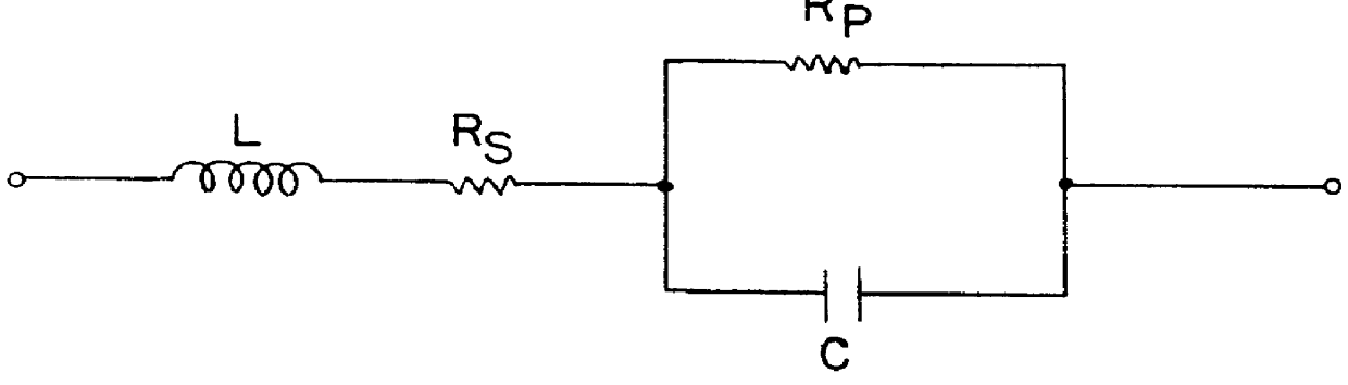
| equivalent series resistance | aaaaa | aaaaa |
Abstract
Description
Claims
Application Information