Organic electroluminescent light emitting devices

a technology of electroluminescent light and electroluminescent light, which is applied in the direction of discharge tube/lamp details, discharge tube luminescnet screens, other domestic articles, etc., can solve the problems of lithium being inferior to the built-up of mgag in terms of safety and reliability, and insufficient film-forming capability, etc., to achieve easy composition control, chemical stability, film-forming ability,

Inactive Publication Date: 2000-09-12
TDK CORPARATION
View PDF17 Cites 55 Cited by
  • Summary
  • Abstract
  • Description
  • Claims
  • Application Information

AI Technical Summary

Problems solved by technology

However, an electron injecting electrode made up of the alkali metal is inferior to that built up of MgAg, etc. in terms of safety and reliability, because the alkali metal has high activity and so is chemically unstable.
When a vacuum evaporation process is used, an AlLi alloy is employed as an Li evaporation source because lithium is in itself inferior in terms of chemical stability, film-forming capability, and adhesion.
A problem with double evaporation is, however, that it is not easy to gain composition control and so it is difficult to obtain the optimum mixing ratio in a stable manner for each batch.
A high Li concentration is a factor in the degradation of devices because the composition is chemically unstable, resulting in deterioration of its film-forming capability and adhesion.
In addition, devices having consistent quality cannot be obtained.
This in turn gives rise to an electron injection efficiency drop, and so renders it difficult to obtain devices having practical enough properties.
An electron injecting electrode film formed by a vacuum evaporation process is poor in denseness, and adhesion to an organic layer interface, yielding an organic EL device with a light emission efficiency drop and dark spots produced by the delamination of the electrode.
Thus, the obtained EL device offers problems in connection with its properties and service life, and the quality of what is displayed on it.
However, this is difficult because, in a rare case alone, the oxide has a lower evaporation temperature or a higher vapor pressure than does a pure metal.
It is thus not easy to form a high-quality electron injecting electrode consisting of a pure metal film.
It is thus impossible to obtain any desired EL properties.
From a practical perspective, the vacuum evaporation process have various productivity problems, among which it is required to make a material replacement or addition within a short time of period, a film having a large area is inconsistent in terms of composition control, film thickness and film quality, and consistent composition control, film quality reproducibility and consistent film quality are not obtained at an increased film forming rate.
Upon direct exposure to air or moisture, however, the alloy electrode oxidizes and corrodes

Method used


Image

  • Organic electroluminescent light emitting devices

Examples


example 1

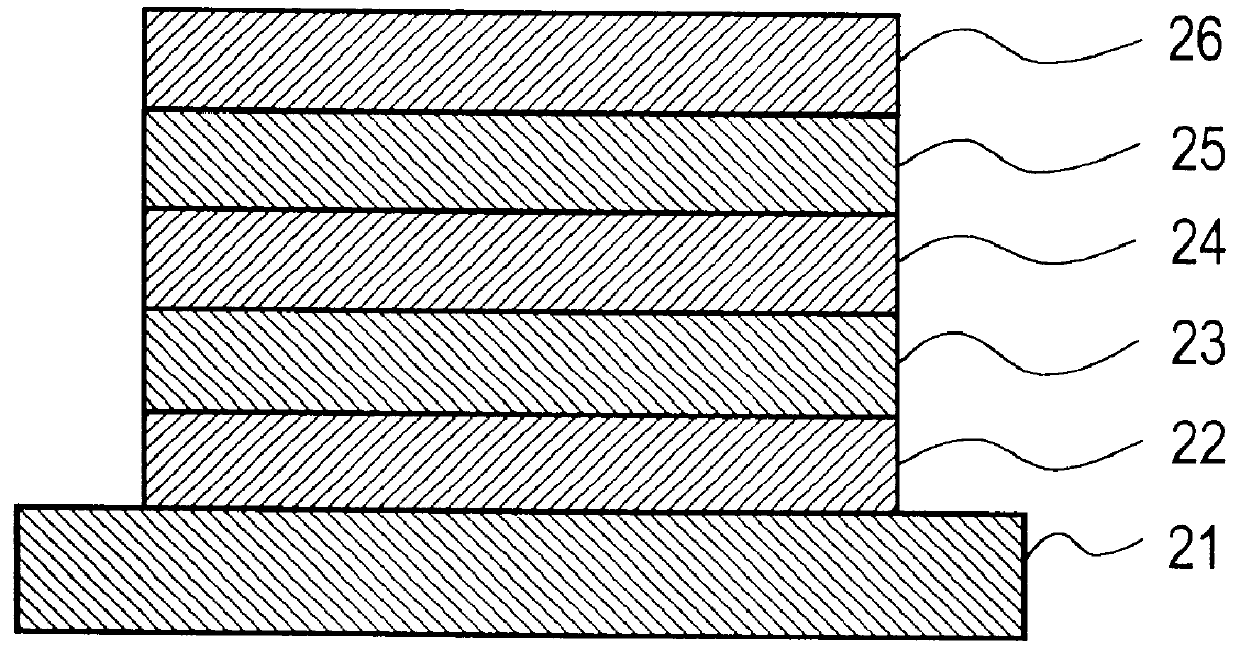
A glass substrate having a 100 nm-thick patterned ITO transparent electrode (a hole injecting electrode) prepared by a sputtering process was ultrasonically washed with neutral detergent, acetone, and ethanol, and then pulled up from boiling ethanol, followed by drying. This substrate was cleaned on its surface with UV / O.sub.3, and fixed to a substrate holder in a vacuum evaporation system, which was evacuated to a vacuum of 1.times.10.sup.-4 Pa or lower. Then, 4,4',4"-tris(-N-(3-methylphenyl)-N-phenylamino)triphenylamine (m-MTDATA) was evaporated at a deposition rate of 0.2 nm / sec. to a thickness of 40 nm to form a hole injecting layer. While the vacuum was maintained, N,N'-diphenyl-N,N'-m-tolyl-4,4'-diamino-1,1'-biphenyl (TPD) was evaporated at a deposition rate of 0.2 nm / sec. to a thickness of 35 nm to form a hole transporting layer. With the vacuum still kept, tris(quinolinolato) aluminum (Alq.sup.3) was evaporated at a deposition rate of 0.2 nm / sec. to a thickness of 50 nm to f...

example 2

An organic EL device was prepared as in Example 1 with the exception that the Li concentration of the AlLi electron injecting electrode was changed to 10.6 at %.

In a dry argon atmosphere, DC voltage was applied across the obtained organic EL device to continuously drive the device at a constant current density of 10 mA / cm.sup.2. In the initial stage, the device was found to emit green light of 550 cd / m.sup.2 (light emission maximum wavelength .lambda.max=530 nm) at 6.6 V. The half time of luminance was 850 hours during which an driving voltage increase of 2.0 V was observed. In this period, nowhere in the device were the occurrence and growth of dark spots of 50 .mu.m or greater in size found.

example 3

An organic EL device was prepared as in Example 1 with the exception that the Li concentration of the AlLi electron injecting electrode was changed to 2.3 at %.

In a dry argon atmosphere, DC voltage was applied across the obtained organic EL device to continuously drive the device at a constant current density of 10 mA / cm.sup.2. In the initial stage, the device was found to emit green light of 520 cd / m.sup.2 (light emission maximum wavelength .lambda.max=530 nm) at 6.7 V. The half time of luminance was 860 hours during which an driving voltage increase of 1.1 V was observed. In this period, nowhere in the device were the occurrence and growth of dark spots of 50 .mu.m or greater in size found.


PUM


Abstract

An organic EL device of the invention comprises a hole injecting electrode, an electron injecting electrode and at least one organic layer interleaved between them. The electron injecting electrode is a film of an aluminum lithium alloy formed by a sputtering technique and comprising 0.4 to 14 at % of lithium. The electron injecting electrode further includes on a side of the electron injecting electrode that is not opposite to the organic layer a protective electrode comprising at least one of aluminum, aluminum and a transition metal except titanium, titanium, and titanium nitride.

Description

The present invention relates generally to an organic electroluminescent light emitting device (which will hereinafter be often called an organic EL device for short), and more particularly to improvements in or relating to an electron injecting electrode for supplying electrons to an light emitting layer, and a protective electrode as well.BACKGROUND TECHNIQUEIn recent years, organic EL devices have been under intensive investigation. One such organic EL device basically includes a transparent electrode (a hole injecting electrode) of tin-doped indium oxide (ITO), etc. A thin film is formed on the transparent electrode by evaporating a hole transporting material such as triphenyldiamine (TPD). A light emitting layer of a fluorescent material such as an aluminum quinolinol complex (Alq.sup.3) is deposited on the hole transporting thin film. An electrode (an electron injecting electrode) is formed thereon from a metal having a low work function such as magnesium or Mg. This organic E...

Claims


Application Information

Patent Timeline
IPC IPC(8): H01L51/52H01L51/50H01B1/16H05B33/26H05B33/12
CPCH01L51/5221Y10S428/917H10K59/8052H10K50/82
Inventor NAKAYA, KENJIKOBORI, ISAMUMORI, MASAMIOHISA, KAZUTOSHIARAI, MICHIO
Owner TDK CORPARATION
Why Eureka
Try Eureka