The use of composites in primary structure in
aerospace applications is limited today because of their relatively high cost.
A significant contribution to the total cost is the
assembly cost where the precured composite elements are assembled, drilled, and fastened.
The necessary design for mechanical fastening complicates the structure, especially in thin sections, because of the need for access to both sides of the bond line.
The bond line lacks any reinforcing material to help with load transfer.
These bonds generally have modest strength, and are susceptible to disbanding with shock
impact or other "
out of plane" forces affecting the assembly.
Such forces often arise in environments prone to vibration.
The
delay from heating and cooling the
mass of the tools adds substantially to the overall time necessary to fabricate each part.
These delays are especially significant when the manufacturing run is low rate where the dies need to be changed frequently, often after producing only a few parts of each kind.
Furthermore, the tooling takes significant time to heat the
composite material to its consolidation temperature and, after curing the composite, to cool to a temperature at which it is safe to remove the finished composite part.
These attempts have shortened the time necessary to produce a composite part, but overall fabrication costs remain high.
Designing and making tools to permit their
active cooling increases their cost.
Such
welding unduly increased the preparation time and the cost for part fabrication.
It also ruined the facesheets (i.e., prohibited their reuse which added a significant cost penalty to each part fabricated with this approach).
Both mechanical fastening and
adhesive bonding are costly,
time consuming assembly steps that introduce excess cost even if the parts that are assembled are fabricated from components produced by an emerging, cost efficient process.
Mechanical fastening requires expensive hole locating, drilling, shimming, and
fastener installation, while
adhesive bonding often requires complicated surface pretreatments.
Access to both sides of the assembly was required in this process which limited its application.
Achieving a uniform, controllable temperature in the bond line, which is crucial to preparing a
thermoplastic weld of adequate integrity to permit use of
welding in
aerospace primary structure, is difficult with conventional susceptors.
Simple as the
thermoplastic welding process sounds, it is difficult to perform reliably and repeatably in a real factory on full-scale parts to build a large structure such as an
airplane wing box.
One difficulty is heating to the bond line properly without overheating the entire structure.
It also is difficult to achieve intimate contact of the faying surfaces of the two parts at the bond line during heating and cooling because of the normal imperfections in the flatness of composite parts,
thermal expansion of the
thermoplastic during heating to the
softening or
melting temperature, flow of the thermoplastic out of the bond line under pressure (i.e., squeeze out), and contraction of the thermoplastic in the bond line during cooling.
Therefore, it is difficult to obtain adequate heating at the bond line between two
graphite or carbon
fiber reinforced
resin matrix composites relying on the susceptibility of the fibers alone as the source of heating in the assembly.
The overheating results in
porosity in the product,
delamination, and, in some cases, destruction or denaturing of the resin.
Overheating the edges of the assembly can result in underheating the center, either condition leading to inferior welds because of non-uniform curing.
These susceptors were difficult to reproduce reliably.
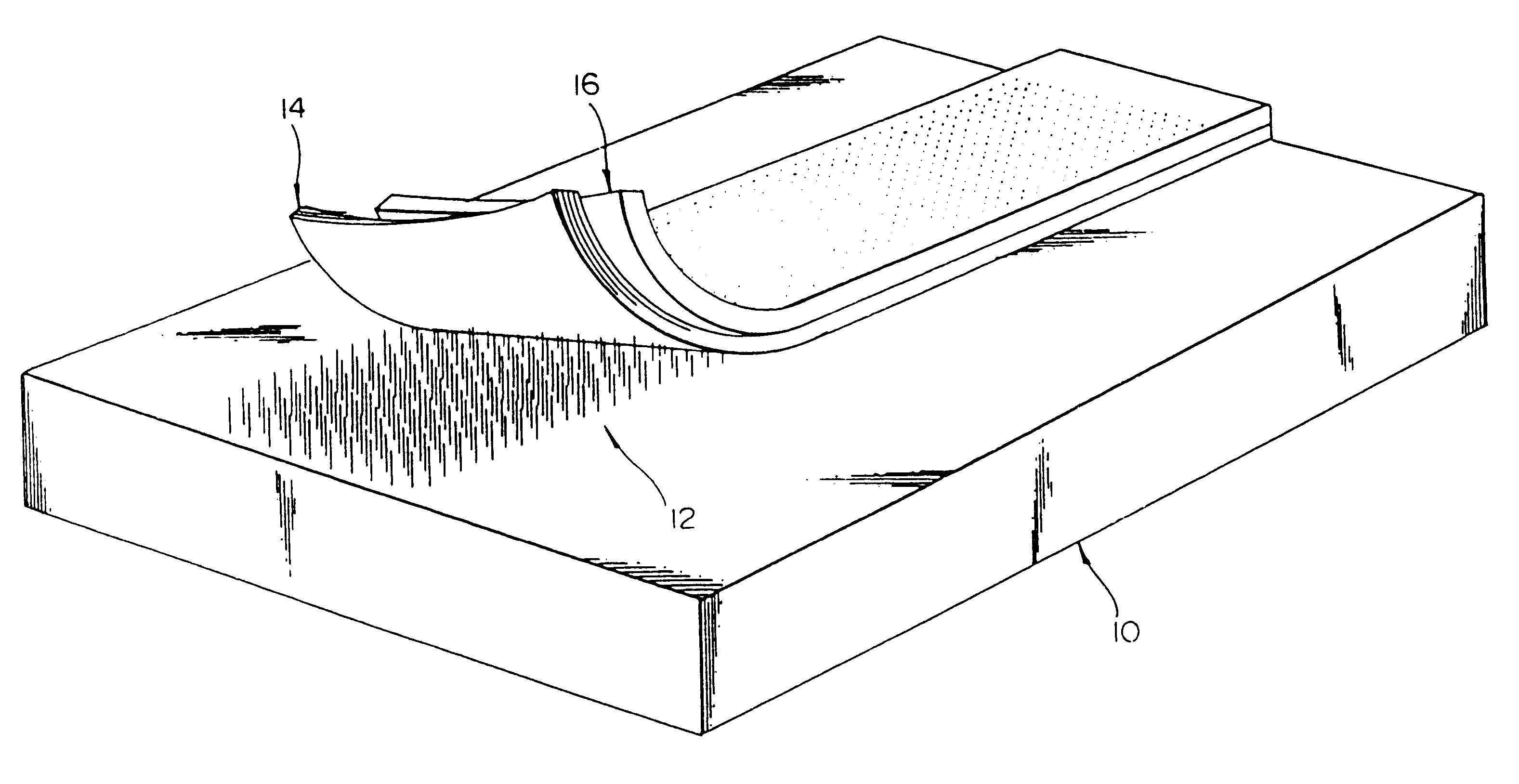
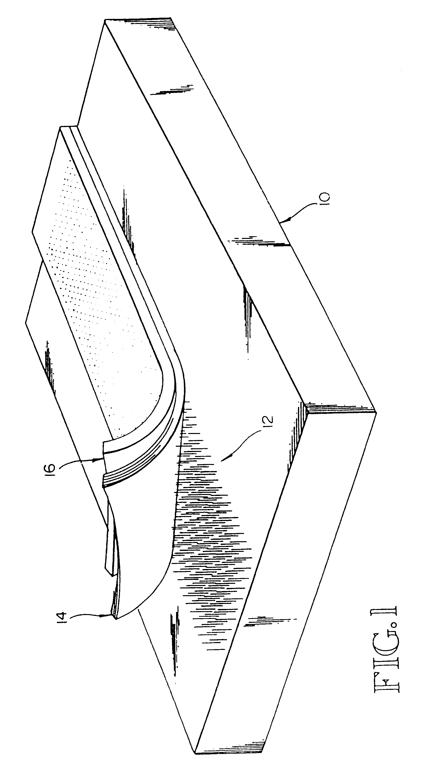
One difficulty in perfecting the process to the point of practical utility for producing large scale aerospace structures in a production environment is control of the surface contact of the faying surfaces of the two parts to be welded together.
The problem involves the timing, intensity, and schedule of heat application so the material at the faying surfaces is brought to and maintained within the proper temperature range for the requisite amount of time for an adequate bond to form.
Parts of this magnitude are difficult to produce with perfect flatness.
These irregularities interfere with full surface area contact between the faying surfaces of the two parts and actually result in surface contact only at a few "high points" across the intended bond line.
Applying pressure to the parts to force the faying surfaces into contact achieves additional surface contact, but full intimate contact is difficult or impossible to achieve in this way.
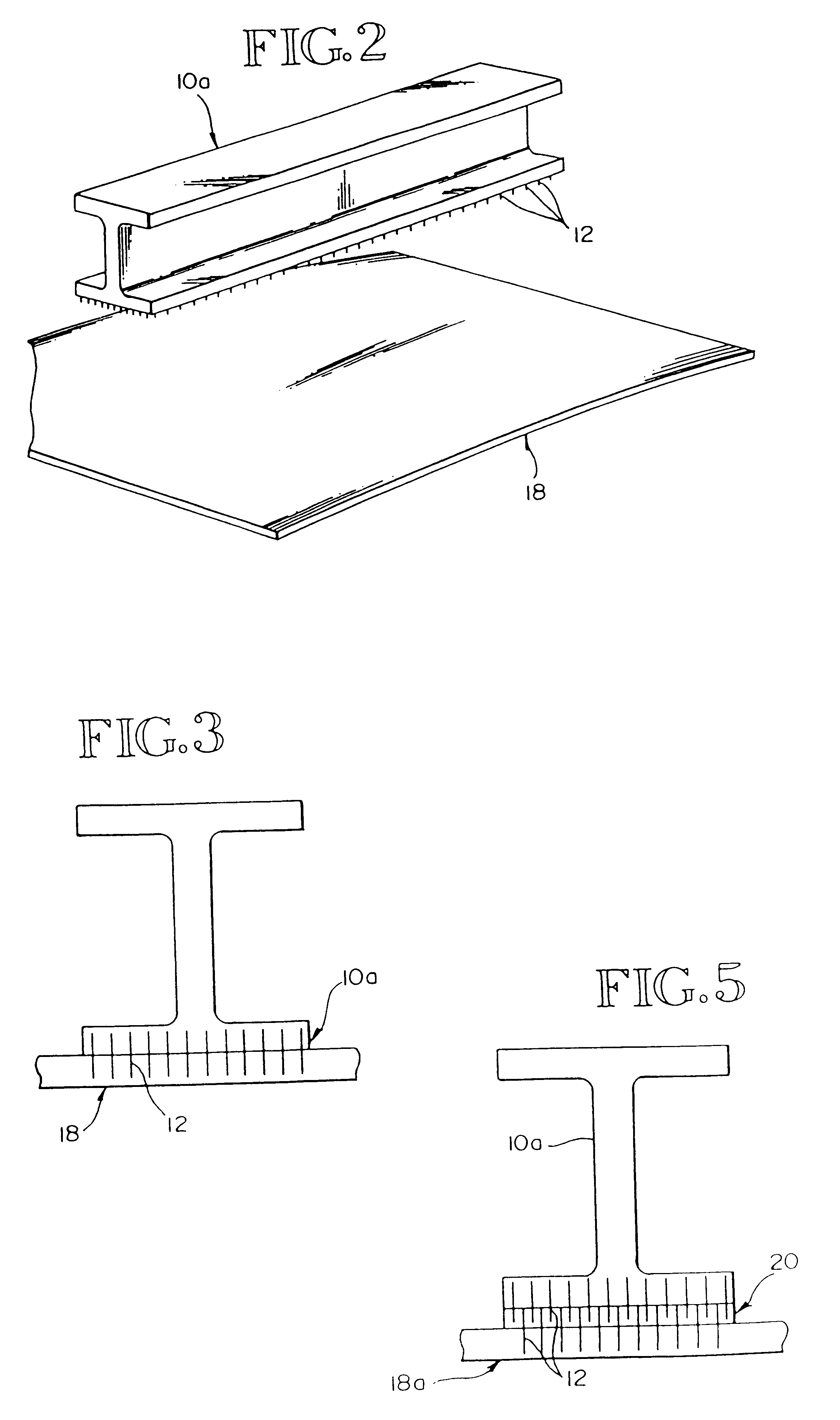
Applying heat to the interface by electrically heating the
susceptor in connection with pressure on the parts tends to flatten the irregularities further, but the time needed to achieve full intimate contact with the use of heat and pressure is excessive, can result in deformation of the top part, and tends to raise the overall temperature of the "I" beam flanges to the
softening point, so they begin to yield or sag under the application of the pressure needed to achieve a good bond.
The need for a
susceptor in the bond line poses many obstacles to the preparation of quality parts.
The
metal which is used because of its high susceptibility differs markedly in physical properties from the resin or
fiber reinforcement so dealing with it becomes a significant issue.
Furthermore, in the bond line, the resin can contact, wet, and bond with the reinforcing
fiber rather than being presented with the resinphilic metal of the conventional systems.
Keeping the facesheets adhered to the foam is problematic.
That is, pulloff strength of the facesheets in shear is low.
Efforts to strengthen the bond have generally focused on improving the
adhesive, but those efforts have had limited success.
In addition to causing layer separation, CTE differences can significantly distort the shape of a structure, making it difficult to maintain overall dimensional stability.
Sandwich structures are desirable because they are usually lighter than
solid metal or composite counterparts, but they may be undesirable if they must be larger or thicker to achieve the same structural performance.
Providing pass-throughs (i.e., holes), which is relatively easy in a
solid metal structure by simply
cutting holes in the desired locations, is more difficult in a composite sandwich structure because holes may significantly reduce the
load carrying capability of the overall structure.
One problem with Childress method is that it requires inserting the Z-pins into the detail parts, which forces modification of their manufacturing processes and tools.

