Laser processing method, method for manufacturing ink jet recording head using such method of manufacture, and ink jet recording head manufactured by such method of manufacture

a technology of laser processing and manufacturing method, which is applied in the direction of recording equipment, manufacturing tools, instruments, etc., can solve the problems of crater formation on the circumference of each hole, prone to collapse of processed shape, and rough edges

Inactive Publication Date: 2004-02-17
CANON KK
View PDF17 Cites 9 Cited by
  • Summary
  • Abstract
  • Description
  • Claims
  • Application Information

AI Technical Summary

Problems solved by technology

With the YAG laser which has been generally in use as a laser processing, edge faces tend to become rough, although drilling is possible.
Also, the CO.sub.2 laser, which is infrared, has a drawback that crater is made on the circumference of each hole.
As a result, the processed shape is liable to be collapsed to make precise processing difficult.
However, the light energy of the laser beams radiated on a work piece is not necessarily used all for cutting the covalent binding of atoms.
Therefore, it becomes difficult to process. metal, ceramics, and minerals (such as silicon) having high ratio of heat transfer, and quartz and glass having low light absorptance.
These have been unavoidable phenomena that may take place when using excimer laser.
Therefore, various processing techniques have been proposed so that these phenomena do not produce unfavorable influences on the recording heads to be used actually.
For example, if an ink jet recording head is assembled with the aforesaid by-product yet to be eliminated, it may cause clogging of discharge ports.
Also, with a part of light energy being converted into thermal energy, a work piece may be caused to expand while it is processed or there is a fear that the work piece tends to be partly fused.
Nevertheless, as described above, no fundamental solution has been given to any one of these techniques.
However, since the phenomena observable for

Method used


Image

  • Laser processing method, method for manufacturing ink jet recording head using such method of manufacture, and ink jet recording head manufactured by such method of manufacture
  • Laser processing method, method for manufacturing ink jet recording head using such method of manufacture, and ink jet recording head manufactured by such method of manufacture
  • Laser processing method, method for manufacturing ink jet recording head using such method of manufacture, and ink jet recording head manufactured by such method of manufacture

Examples


first embodiment

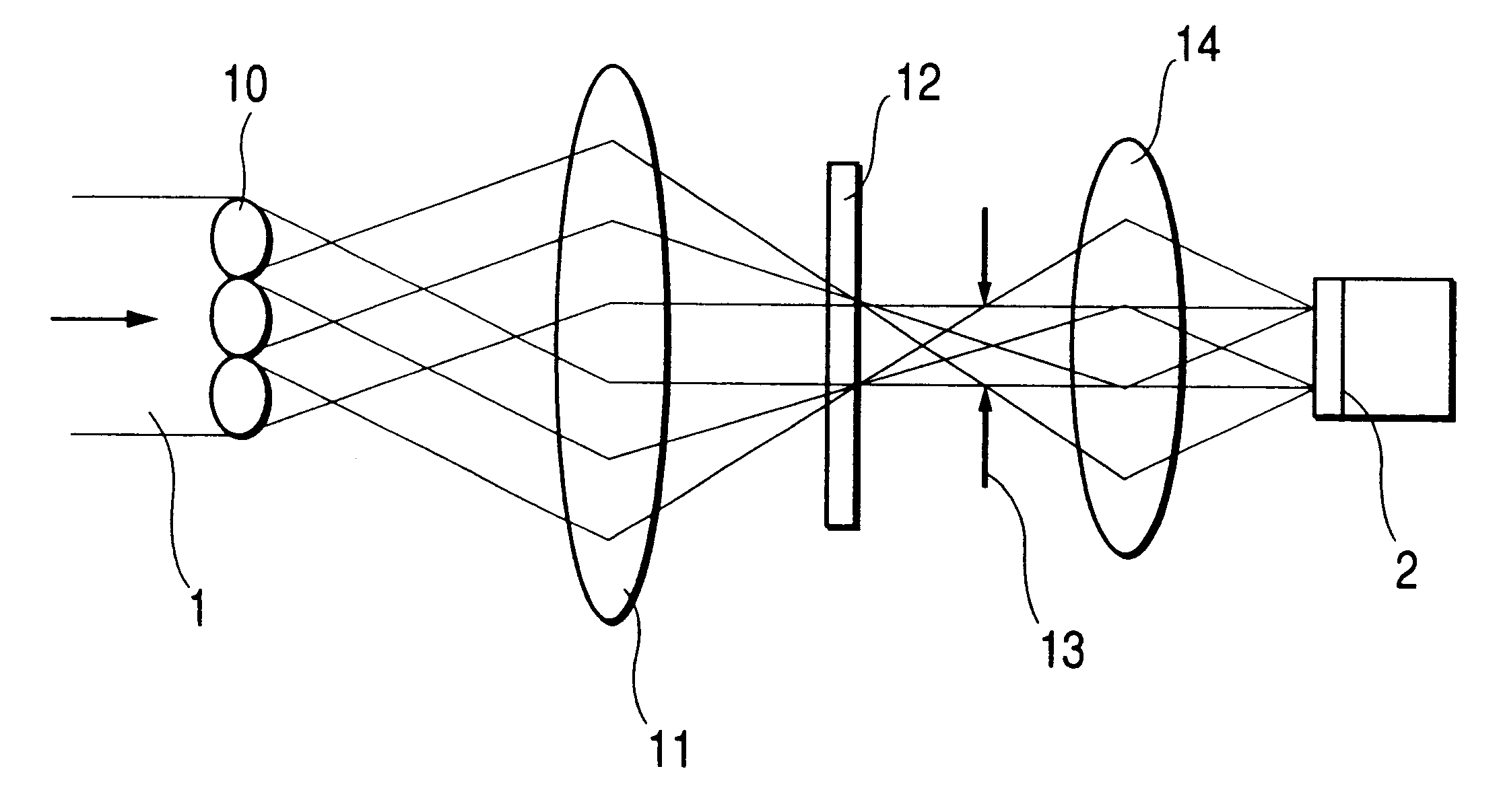
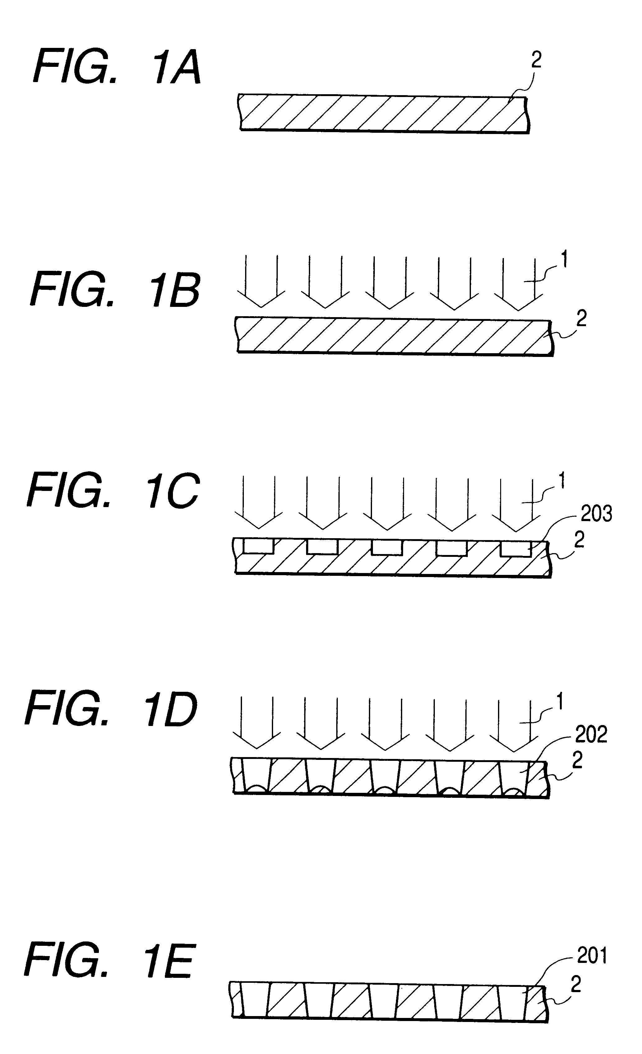
FIGS. 1A to 1E are views which schematically illustrate a method for processing ink discharge ports of an ink jet recording head in accordance with a first embodiment of the present invention. In FIGS. 1A to 1E, the progressive states of process in this method are schematically shown as the time elapses.

In FIG. 1A, a reference numeral 2 designates a resin plate which is the basic material used for the formation of ink discharge ports. Then, as shown in FIG. 1B, the laser beams 1 that irradiate light are radiated on the resin plate 2 in a configuration of plural discharge ports through the mask having a plurality of opening patters formed at predetermined intervals so that the arrangement density of the discharge ports become 900 dpi. Here, in accordance with the present embodiment, the femtosecond laser is used on the following condition: the irradiating laser beams are near infrared rays having the wavelength of 775 nm; the width of radiation pulse time is 150 femtoseconds per puls...

second embodiment

FIGS. 4A to 4D and FIGS. 5E to 5G are views which illustrate the steps of processing a cantilever to be manufactured by laser processing in accordance with a second embodiment of the present invention.

Now, the description will be made of the method for manufacturing an electrostatic type cantilever in accordance with FIGS. 4A to 4D and FIGS. 5E to 5G.

In FIG. 4A, a basic member is prepared in such a manner that an aluminum thin film 42 is formed on a silicon base plate 41 by use of vapor deposition or sputtering. Then, a resin film 43 (actually, a resist film) is coated on it by means of spin coating.

Then, in the step shown in FIG. 4B, the resin film 43 is locally removed by the radiation of patterning laser to form the electron contact surface A. Then in the step shown in FIG. 4C, a metallic film 44 (an elastic metal film such as aluminum or copper) is formed by means of vapor deposition.

Then, as shown FIG. 4D, with the radiation of ultrashort pulse laser having a predetermined patt...

third embodiment

FIGS. 6A to 6C are views which illustrate the steps of processing the ink discharge ports to be manufactured by laser processing in accordance with a third embodiment of the present invention.

Now, the description will be made of the method for processing to form ink discharge ports 40 on the orifice plate 60 of an ink jet recording head in accordance with FIGS. 6A to 6C.

In FIG. 6A, an orifice plate member is prepared by inserting a thin copper foil 62 into the polysulfone sheet 61.

With the insertion of the copper foil 62 into the polysulfone sheet 61, the following can be achieve, among some others:

(1) The thermal expansion of the polysulfone sheet is made as close as possible to that of the silicon IC base plate 80 where the silicon ceiling plate 70 constituting the ink flow paths, ink liquid chamber, and the like of the ink jet main body, and ink discharge pressure generating elements 81 are incorporated, thus making it possible to prevent a drawback from taking place on the bondi...


PUM

PropertyMeasurementUnit
Timeaaaaaaaaaa
Timeaaaaaaaaaa
Wavelengthaaaaaaaaaa

Abstract

A laser processing method for performing laser ablation process on a work piece by radiating laser beam on the work piece includes the step of forming simultaneously a plurality of process shapes arranged at a predetermined interval by use of laser beam of plural pulses having extremely large spatial and temporal energy density radiated from a laser oscillator as the laser beam oscillating at the pulse radiation time of one picosecond or less. With the laser processing method thus structured, it is possible to perform a highly precise processing without creating by-product, as well as to fundamentally prevent the converted thermal energy from being accumulated on a work piece, such as resin, which causes the work piece to be fused or thermally expanded during the operation of laser processing.

Description

1. Field of the InventionThe present invention relates to a laser processing method. More particularly, the invention relates to a method of manufacture that uses such laser processing, for example, to manufacture an ink jet recording head for enabling ink droplets to fly and adhere to a recording medium, and also, relates to an ink jet recording head manufactured by such method of manufacture.2. Related Background ArtConventionally, there has been known the laser processing method that uses ultraviolet laser in order to precisely process a structural object that requires minute structures formed in high precision.As an example of such precise processing, there is such one as processing ink flow paths or ink discharge ports of an ink jet head.In the specification of Japanese Patent Application Laid-Open No. 2-121842 or 2-121845, is disclosed the high precision processing of ink flow paths or ink discharge ports using excimer layer, the typical ultraviolet laser.In other words, the e...

Claims


Application Information

Patent Timeline
IPC IPC(8): B23K26/40B23K26/00B23K26/06B41J2/15B41J2/145B41J2/16B41J2/005
CPCB23K26/0635B23K26/0656B23K26/4005B23K26/401B23K26/4065B23K26/407B41J2/15B41J2/1601B41J2/1607B41J2/162B41J2/1623B41J2/1626B41J2/1634B41J2002/14379B41J2002/14387B23K26/0624B23K26/066B23K26/40B23K2103/54B23K2103/08B23K2103/42B23K2103/50B41J2/005
Inventor KOIDE, JUN
Owner CANON KK
Why Eureka
Try Eureka