Voltage and light induced strains in porous crystalline materials and uses thereof

a technology of porous crystalline materials and strains, which is applied in the selection of device materials, generators/motors, instruments, etc., can solve the problems of complex construction, slow progress of deformable mirrors, and heating created by flowing currents

Inactive Publication Date: 2004-04-27
TECHNION RES & DEV FOUND LTD
View PDF3 Cites 109 Cited by
  • Summary
  • Abstract
  • Description
  • Claims
  • Application Information

AI Technical Summary

Problems solved by technology

Despite large efforts made in the last few decades, progress in deformable mirrors has been slow, and there are only a few kinds available.
The high price of these mirrors is an indicator of the problems in their manufacture, such as complex construction, non-repeatability and non-uniformity.
The drawback here is the heating created by the flowing current.
Severe drawbacks such as requirements for both a hydraulic system and an electrical one, slow response and large volume make them less convenient to employ.
Unfortunately, they cannot mimic the aberrated wave front too well, and they have gaps between the mirrors.
1. Yield or backlash below the required wave front accuracy (usually below 0.1 micrometer in the normal direction, 0.5 micrometer inside the plane of the face sheet).
2. Possibility for simple and accurate replacement of a faulty actuator (this is especially important for multiple element mirrors).
3. Foot-print (projected area of the actuator on the mirror) allowing high density of elements. The base attachment foot-print also has to allow power lines to the actuator.
4. Print-through (induced local mirror aberration) at the required wave front accuracy (say 0.1 micrometer) at all lateral scales which cannot be corrected by the actuators themselves.
5. Adjustment for zero power: means to set the mirror surface flat if the actuators are not powered (the telescope must still function when the deformable mirror is turned off). In some cases this adjustment can be achieved by a constant bias on the elements, which reduces the dynamic range of the actuators. In these cases the zero adjustment can be coarser and only place the actuator in its application margin.
6. Preloading of the actuators is sometimes required. Piezoelectric actuators, for example, function better against pressure.
7. The three-dimensional shape of the attachment is extremely important for tailoring an appropriate influence function.
8. The frequency response of the structure has to be as linear as possible, and the first resonance frequency high above the atmospheric fastest fluctuations.
If each actuator has a three dimensional influence function of its own, than the control computer must perform a very large and time consuming fit of the whole wave front to the whole mirror.
Even influence functions whose size is larger than the actuator-to-actuator distance complicate this calculation.
Deformable mirrors which use piston actuation tend to have thicker face plate, since the available force is usually much more than required (although the stroke might be limited).
Both cases allow longer strokes, but are limited in force and have rather high acoustic pick-up.
Too tight a space is also a problem since the air has no room to escape when the membrane moves.
This method is limited due to the fragile nature of the ceramic piezoelectric material that does not allow two high a ratio of the diameter to the thickness.
Since the dynamic range of the stroke of most piston mirrors is quite limited, this low order aberration is often taken care of separately by a steering mirror.
Unfortunately, these qualities make the mirrors extremely complex to construct, maintain, and run.
A limiting factor in the design of deformable mirrors is their drivers or amplifiers.
Their drivers, running in parallel (one each for an actuator), a large volume and create a great amount of heat which has to be disposed off away from the telescope.
In low-porosity materials, the residual matter is not made of separate islands, and thus its conduction is high and the application of voltage to it results in short-circuiting between the electrodes (percolation).

Method used


Image

  • Voltage and light induced strains in porous crystalline materials and uses thereof
  • Voltage and light induced strains in porous crystalline materials and uses thereof
  • Voltage and light induced strains in porous crystalline materials and uses thereof

Examples


example 1

Construction of a Mirror

The mirror was constructed of a silicon wafer, polished on both sides, whose front (mirror) side was evaporated with a reflective layer and the wafer was annealed at 450.degree. C. for approximately 30 minutes. 1" or 2" n-type wafers were used, with a diameter of the porous area of 0.5" and 1". The back side of the wafer was made porosive by etching in HF:ehanol (1:1) solution, with the HF itself dissolved in water (1:1). An initial current of 120-130 mA, (24 mA / cm.sup.2) was applied to the sample, while it was illuminated by a 50 W halogen lamp. The etching lasted for about 35 minutes, which sets the thickness of the porous layer to 50 micrometers. The sample was washed a few times by ethanol, then left in ethanol for 30 minutes for final removal of the HF. It was then passivated by growing oxygen on the porous layer, in oxygen atmosphere for 30 minutes at 450.degree. C. This is a standard processing technique of silicon wafers, and requires rather a simple ...

example 2

Theoretical Consideration

Another way to look at the mirror is to think about it as a set of pistons operating parallel to the surface of the mirror, pulling the elements towards each other and creating bending moments.

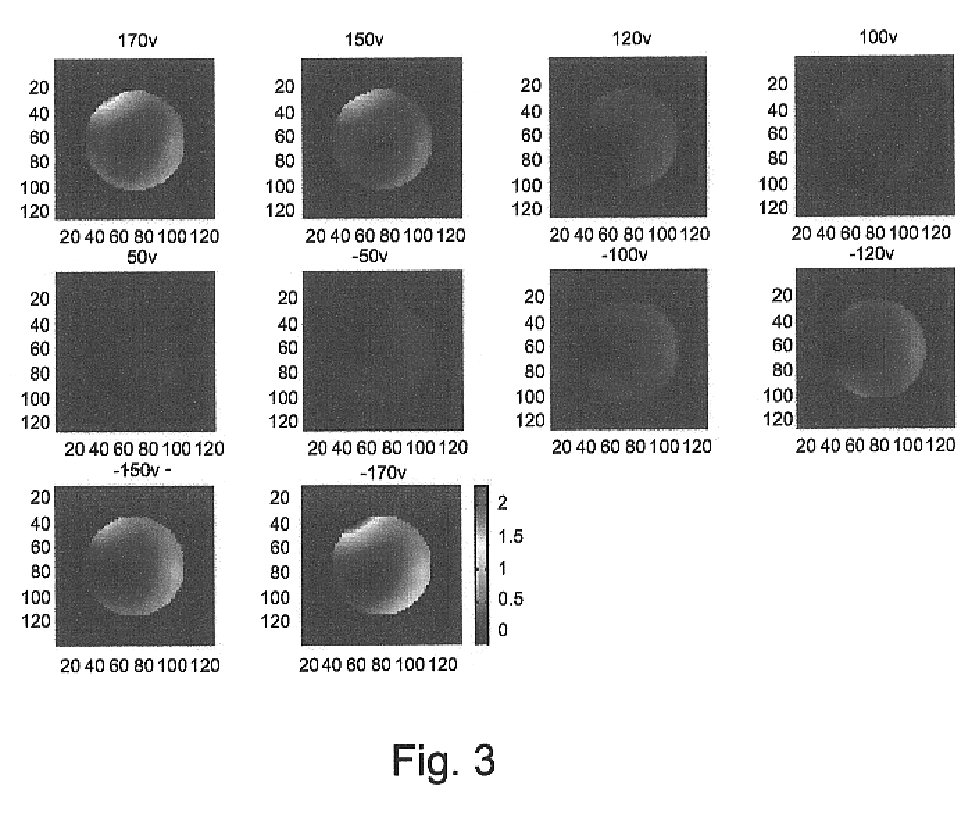
The strain of a plate made of two such layers can be shown to follow the biharmonic equation, which can further be reduced to the harmonic (Poisson) equation for simple boundary conditions. Since in electrostatic pull the stress is proportional to the square of the voltage, the reflected wave front excursions W(r) (equal to twice the strain) are assumed to follow:

.gradient..sup.2 W(r)=.gamma.[dV(r)+mV.sup.2 (r)]

where V(r) is a continuous description of the voltage on the electrodes. d and m the piezoelectric and electrostrictive constants, and .gamma. depends on geometrical factors and Poisson's ratio and Young modulus of the porous silicon and crystal silicon[C. Schwartz, E. Ribak, and S. G. Lipson, `Bimorph adaptive mirrors and curvature sensing`, J. Opt. Soc. Am. A ...

example 3

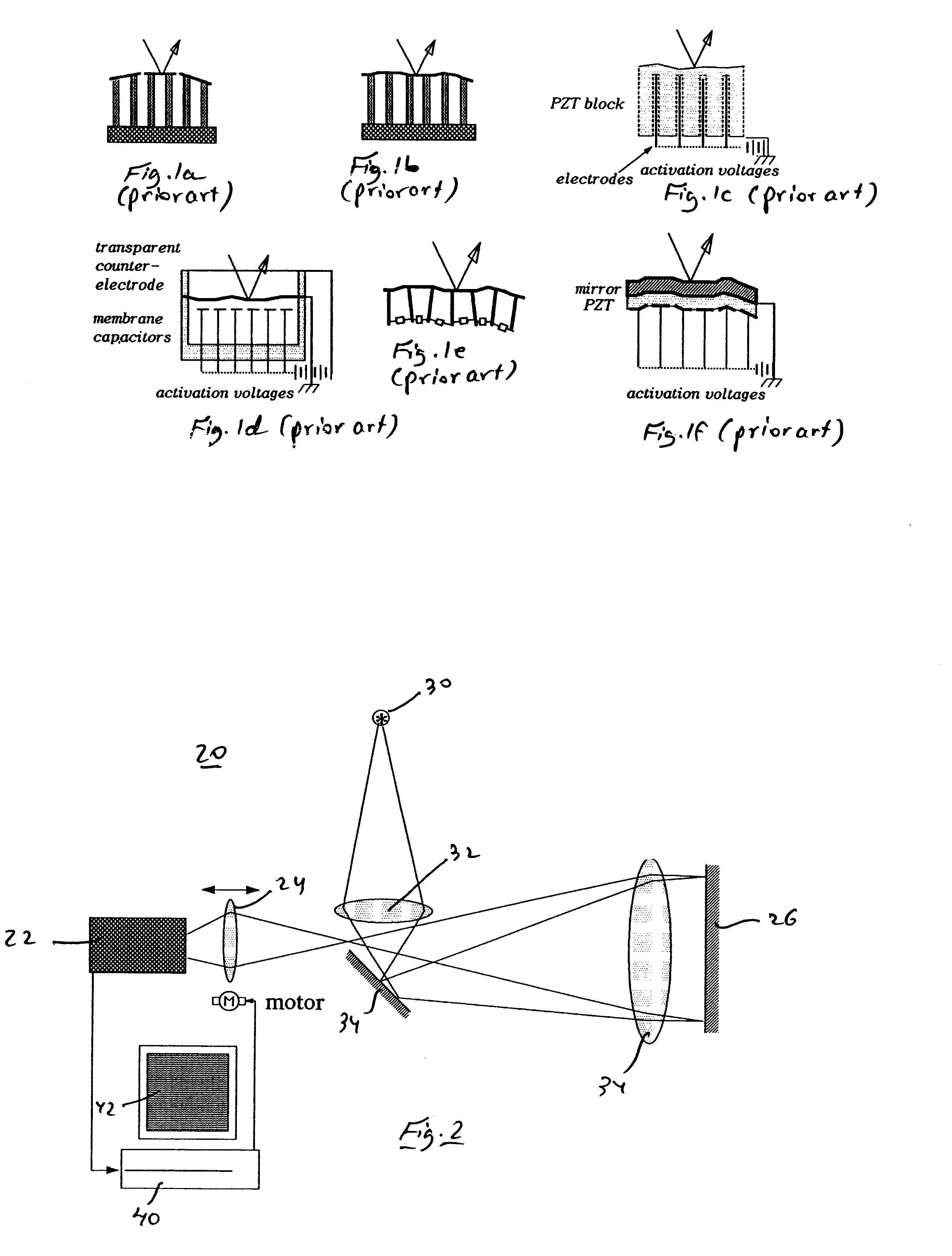
An Optical System Incorporating the Mirror

Referring now to FIG. 2, a simple optical system 20 was constructed that allows one to re-image different planes on a camera 22. System 20 includes a point source 30 and a lens 32 so as to focus light just before a surface of a mirror 34. Mirror 34 is so positioned so as to reflect the light through a collimating lens 34 onto a sample 26, which is a mirror in accordance with the teachings of the present invention made and constructed as described hereinabove, and from which the light is reflected back through lens 34 to a motorized (M) focusing lens 36 which focuses the light onto a CCD camera 22. By moving lens 24 in front of camera 22, one can choose two planes to overlap (before and after reflection from sample 26), or at any two other locations using a frame grabber 40 and an appropriate computer 42 and software.

In order to find the response of the mirror to voltage, it is easier to focus one of the locations at the mirror surface itself...


PUM

PropertyMeasurementUnit
refractive indexaaaaaaaaaa
thick n-typeaaaaaaaaaa
current densityaaaaaaaaaa

Abstract

A piezoelectric device is disclosed, which includes a first element of porous crystalline material, a second element being attached to, or integrally formed with, the first element, and at least one electrode being in electrical contact with the first element, such that subjecting the first element to an electric potential via the at least one electrode results in a strain induced by the first element on the second element. Also disclosed is a piezooptic device which includes a first element of porous crystalline material, a second element being attached to, or integrally formed with, the first element, and a light source, such that subjecting the first element to light originating from the light source results in a strain induced by the first element on the second element.

Description

FIELD AND BACKGROUND OF THE INVENTIONThe present invention is derived from a striking novel discovery, that porous crystalline materials have piezoelectric and piezooptic properties. The present invention, therefore, relates to devices and methods which take advantage of this newly discovered phenomenon. One main use of this discovery is in the field of adaptive optics, e.g., adaptive reflectors such as mirrors, however, other uses, as is further delineated below, are anticipated. Thus, for example, the new technology can find uses in (i) attached fiber optics maneuvering (movement of fiber for focusing, etc.); (ii) attached fiber optic bending for mode control; (iii) attached fiber optics intensity and polarization control; (iv) spatial light modulation (electro optical and opto-optical modulation) by adjustment of specific elements or a whole device; (v) tunneling devices, where the tunneling current is sensitive to distance between elements; (vi) scanning microscopy heads, optica...

Claims


Application Information

Patent Timeline
Patent Type & Authority Patents(United States)
IPC IPC(8): G02B26/08H01L41/18H01L41/00H01L41/09
CPCG02B26/0825H01L41/00H01L41/18H01L41/0973H10N30/00H10N30/2047H10N30/85
Inventor RIBAK, EREZ N.
Owner TECHNION RES & DEV FOUND LTD
Why Eureka
Try Eureka