Interconnect module with reduced power distribution impedance

Inactive Publication Date: 2005-01-25
3M INNOVATIVE PROPERTIES CO
View PDF36 Cites 110 Cited by
  • Summary
  • Abstract
  • Description
  • Claims
  • Application Information

AI Technical Summary

Benefits of technology

In general, the invention is directed to interconnect modules that incorporate a thin, high dielectric constant capacitor structure to provide reduced impedance power and ground distribution, as well as processes for manufacturing such interconnect modules. An interconnect module constructed in accordance with the invention is capable of reliably attaching an integrated circuit chip to a printed wiring

Problems solved by technology

As frequencies increase, however, it becomes increasingly difficult to achieve adequately low impedance due to the inherent series inductance produced by the discrete capacitors.
In addition, leads, solder bumps, vias, plated through holes, and traces in the interconnect module compound the inability of the discrete capacitors to function adequately at higher frequencies due to increased inductance.
Unfortunately, on-chip capa

Method used


Image

  • Interconnect module with reduced power distribution impedance
  • Interconnect module with reduced power distribution impedance
  • Interconnect module with reduced power distribution impedance

Examples


example 1

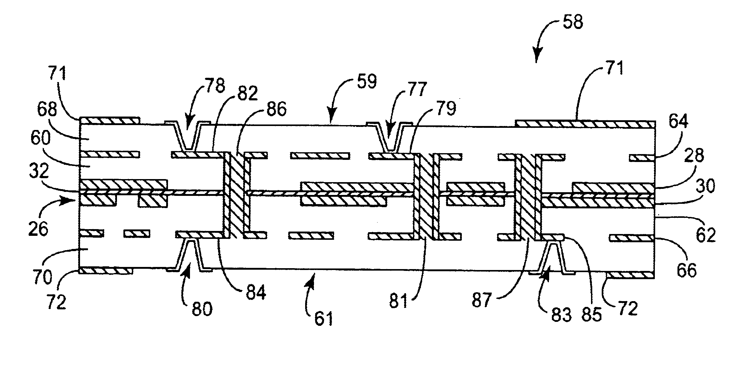
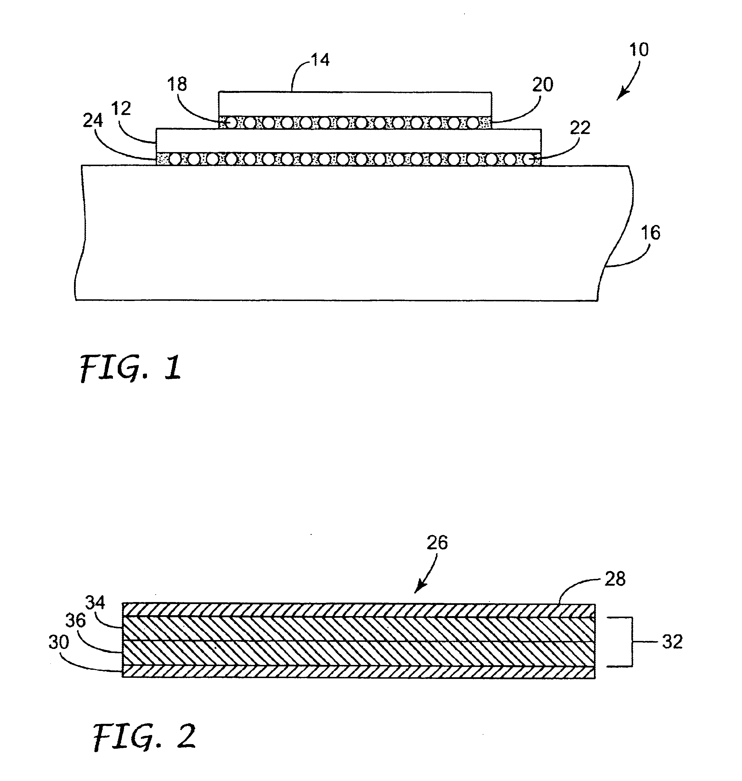
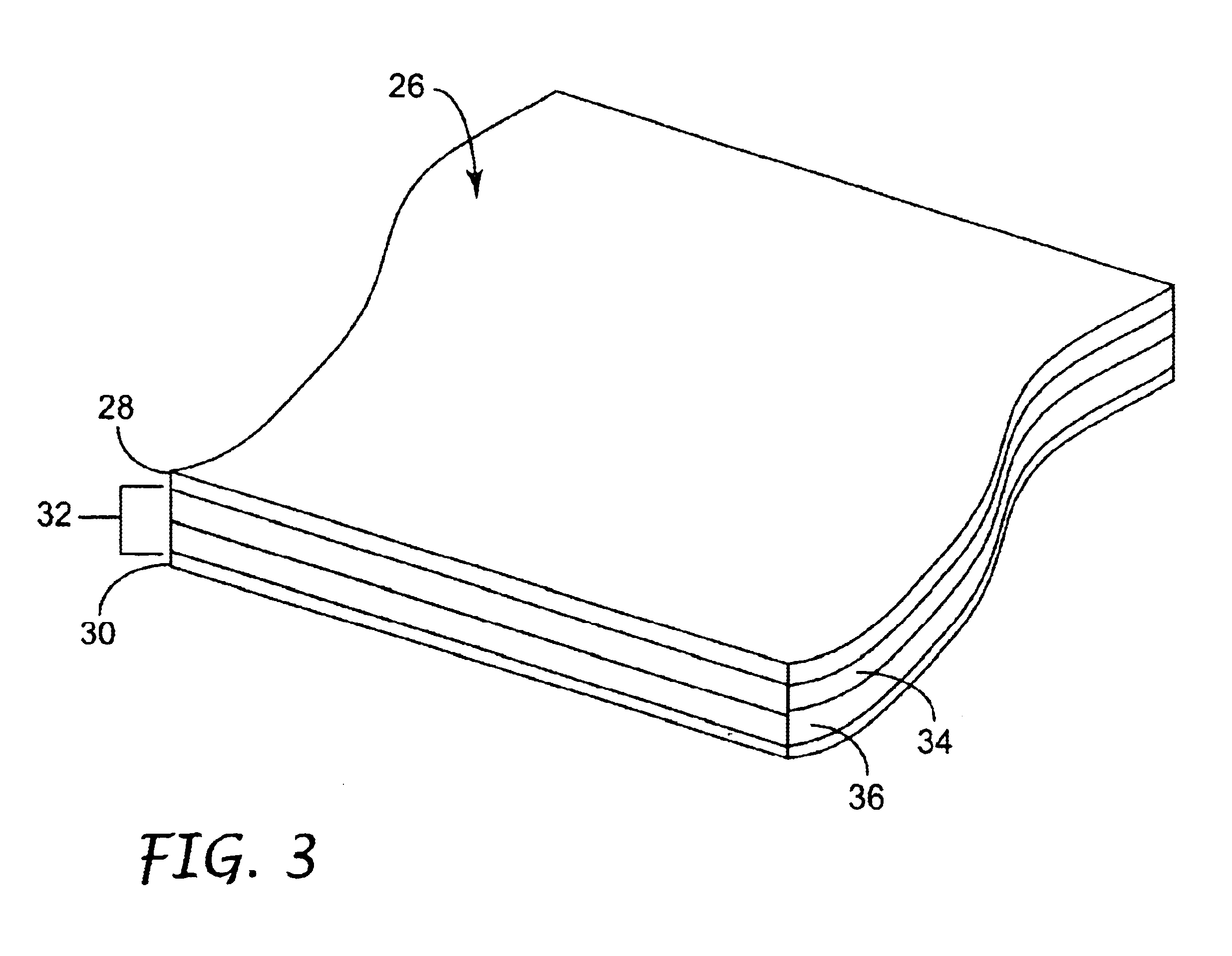
Basic methods suitable for manufacturing interconnect modules with cross sections as described herein are disclosed in U.S. Pat. Nos. 5,879,787 and 6,021,564, as mentioned above. The following example describes a representative method for additionally producing a patterned high dielectric constant laminate, i.e., a capacitor structure as described with reference to FIGS. 1-7 above, for incorporation in an interconnect module to achieve reduced power distribution impedance. This example involves the use of a laminated capacitor structure comprising approximately 18 micron copper foil on either side of a high dielectric constant material that is approximately 8 microns in thickness.

First, the capacitor structure is formed. Copper foil substrates available from Carl Schenk A G, Nurenberg, Germany, are provided having a thickness of 18 microns, an anneal temperature of 140° centigrade and an average surface roughness (RMS) of 8 nm. Chemisorbed materials are removed in an oxygen / argon pl...

example 2

In another example, capacitor structure was formed with a dispersion as described in above-referenced U.S. application Ser. No. 09 / 902,302. In particular, a dispersion as indicated below in Table 2 was coated onto a copper foil using a gravure or die coating technique.

TABLE 2ComponentGramsEpon ® 1001F epoxy + Epon ® 1050 epoxy16.09,9-bis(3-chloro-4-aminophenyl) fluorine4.0Barium Titanate, 0.2 micron (Cabot Performance Materials)78.7PS3 polyester / polyamine copolymer dispersant (Uniquema)1.35-aminobenzotriazole0.08

Dry thicknesses of the dielectric ranged from approximately 2.0 to 5.0 microns. The coating was dried to a tack-free surface, and then wound into rolls. Two rolls were laminated, coated side by side, using two heated nip rollers. A standard photoresist laminator was used. The laminated material was cured at 180 degrees centigrade for 1.5 to 2.5 hours. The cured panels were patterned on one or both sides using conventional photoresist and etchant to produce individual capacit...

example 3

As another example of the fabrication of a capacitor structure suitable for use in an interconnect module, a dispersion as described in above-referenced U.S. application Ser. No. 09 / 902,302 and Table 3 below was coated onto a copper foil.

TABLE 3ComponentGramsaGramsbEpon ® 1001F epoxy20.216.2Epon ® 1050 epoxy5.04.09,9-bis(3-chloro-4-aminophenyl) fluorine05.1Barium Titanate, 0.2 micron100100(Cabot Performance Materials)PS3 polyester / polyamine copolymer1.81.8dispersant (Uniquema)Methyl ethyl ketone / methyl isobutyl ketone (4:6)1271272,4,6-tris(dimethylaminomethyl)phenol0.250.025 or 0aStandard formulation using only 2,4,6-tris(dimethylaminomethyl)phenol catalyst as the curing agent b9,9-bis(3-methyl-4-aminophenyl)fluorene was also used.

The above dispersions were coated using a gravure or die coating technique. Adhesion promoting agents may be coated onto the substrate prior to coating by the epoxy. Typically, a dilute solution, e.g., 0.05 to 0.15% by weight in an alcohol such as methano...


PUM

PropertyMeasurementUnit
Lengthaaaaaaaaaa
Thicknessaaaaaaaaaa
Thicknessaaaaaaaaaa

Abstract

An interconnect module for an integrated circuit chip incorporates a thin, high dielectric constant embedded capacitor structure to provide reduced power distribution impedance, and thereby promote higher frequency operation. The interconnect module is capable of reliably attaching an integrated circuit chip to a printed wiring board via solder ball connections, while providing reduced power distribution impedance of less than or equal to approximately 0.60 ohms at operating frequencies in excess of 1.0 gigahertz.

Description

TECHNICAL FIELDThe invention relates to interconnect modules for use with integrated circuit chips.BACKGROUNDMulti-layered interconnect modules are widely used in the semiconductor industry to mechanically support integrated circuit chips and electrically attach the chips to printed wiring boards. Interconnect modules can be configured to support a single chip or multiple chips, and are typically identified by the designation SCM (single chip module) or MCM (multi-chip module).An interconnect module provides interconnections that serve to electrically couple an integrated circuit chip to signal lines, power lines, and other components carried by a printed wiring board. In particular, the interconnect module provides interconnections that redistribute the densely packed inputs and outputs (I / Os) of the chip to corresponding I / Os on the printed wiring board. In addition to electrical interconnection, an interconnect module typically serves to mechanically couple a chip to a printed wi...

Claims


Application Information

Patent Timeline
IPC IPC(8): H05K1/16H05K3/00H05K3/46H05K3/42H05K1/14H05K1/11H01L21/48H01L21/60H01L23/498H01L23/50H01L23/64H01L23/12H01L23/66
CPCH01L21/4857H01L23/49827H01L23/50H01L23/642H01L23/66H05K1/162H01L23/49822Y10T29/49165H01L24/81H01L2224/8121H01L2224/81815H01L2224/83102H01L2224/92125H01L2924/01078H01L2924/01079H01L2924/15311H01L2924/3011H05K1/113H05K1/141H05K3/0035H05K3/429H05K3/4602H05K3/4688H05K2201/0112H05K2201/0209H05K2201/0355H05K2201/049H05K2201/09309H05K2201/09509H05K2201/09536H05K2201/0959H05K2201/09672H05K2201/09718H05K2201/10734H05K2203/1383H01L2924/01019H01L2924/01068H01L2924/01084H01L2224/16225H01L2224/32225H01L2224/73204Y10T29/49155Y10T29/4913H01L2924/00H01L2924/00013H01L2924/12042H01L2924/14H01L2224/81205
Inventor SYLVESTER, MARK F.HANSON, DAVID A.PETEFISH, WILLIAM G.
Owner 3M INNOVATIVE PROPERTIES CO
Why Eureka
Try Eureka