System for cardiac procedures

a cardiac procedure and system technology, applied in the field of devices and methods, can solve the problems of significant complications, increased mortality and morbidity for reoperation, and weeks of hospitalization and months of recuperation time, so as to reduce hospitalization and recovery time, reduce mortality and morbidity, and reduce patient suffering

Inactive Publication Date: 2005-03-15
EDWARDS LIFESCIENCES LLC
View PDF73 Cites 398 Cited by
  • Summary
  • Abstract
  • Description
  • Claims
  • Application Information

AI Technical Summary

Benefits of technology

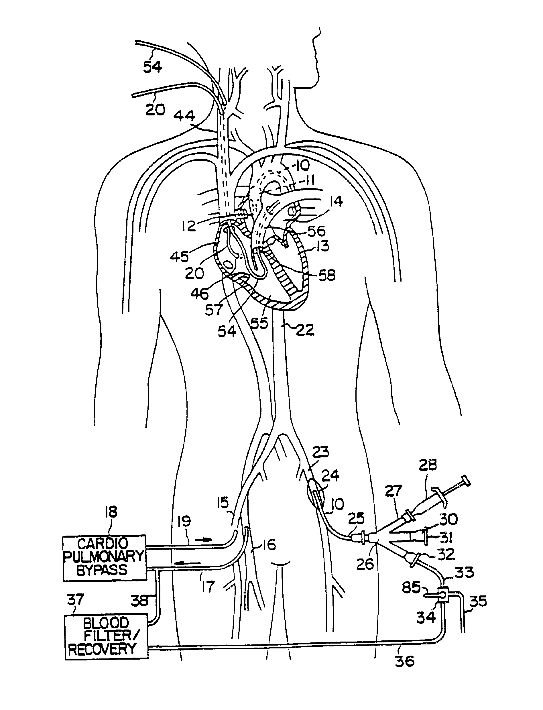
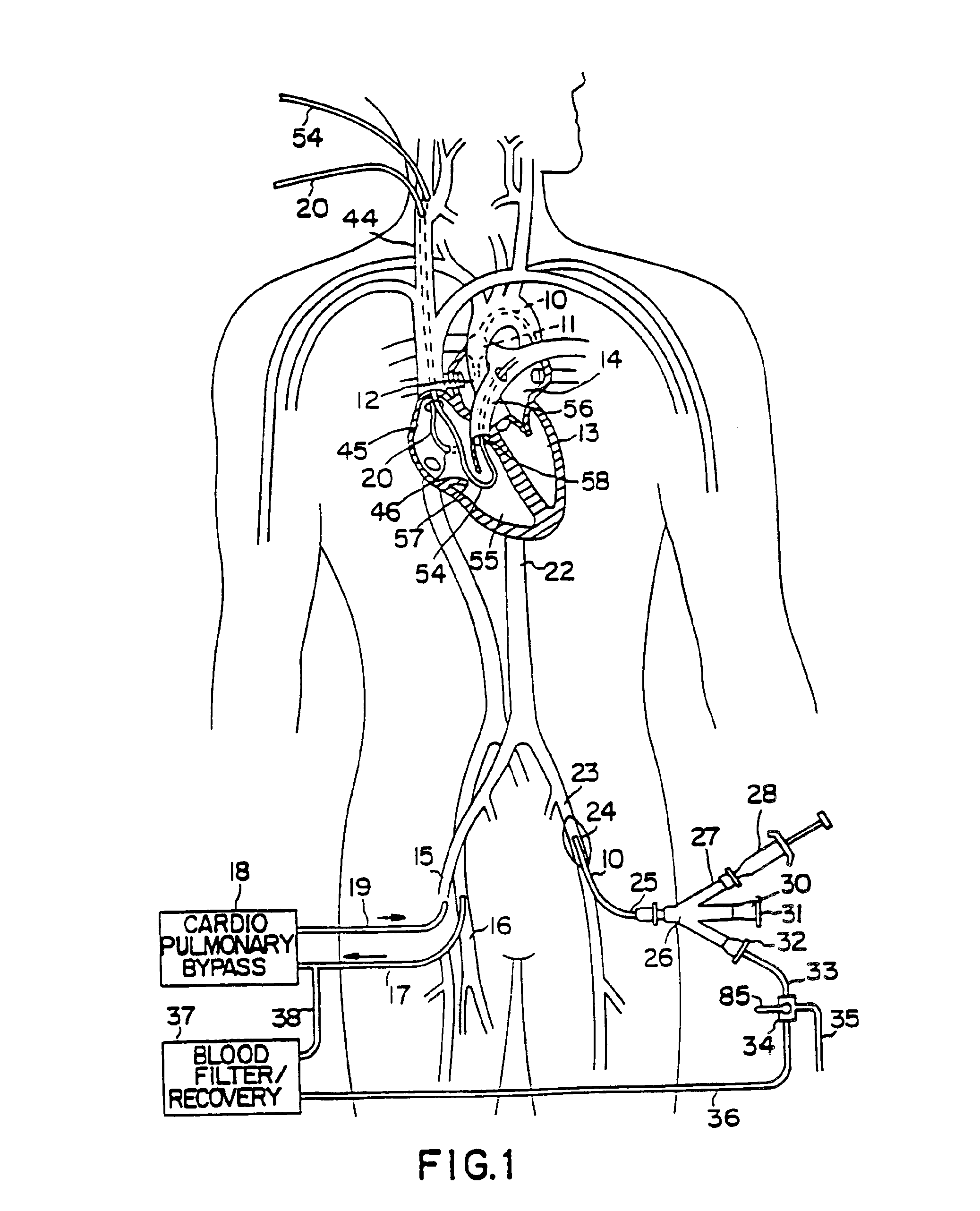
Thus, using the system and method of the invention, a patient's heart can be arrested and the patient placed on cardiopulmonary bypass without a conventional gross thoracotomy, thereby reducing mortality and morbidity, decreasing patient suffering, reducing hospitalization and recovery time, and lowering medical costs relative to previous open-chest procedures. The endovascular partitioning device of the invention permits blood flow through the ascending aorta to be completely blocked between the coronary ostia and the brachiocephalic artery in order to isolate the heart and coronary arteries from the remainder of the arterial system. This has significant advantages over the aortic cross-clamps used in current cardiac procedures, not only obviating the need for a gross thoracotomy, but providing the ability to stop blood flow through the aorta even when calcification or other complications would make the use of an external cross-clamp undesirable. Moreover, the device and method of the invention accomplish this with a minimum of arterial penetrations, thereby minimizing trauma and the risk of complications such as infection.
The system and method of the invention may further be useful to provide cardiopulmonary bypass during endovascular interventional procedures in which cardiac function may or may not be arrested. Such procedures may include angioplasty, atherectomy, heart valve repair and replacement, septal defect repair, treatment of aneurysms, myocardial mapping and ablation, myocardial drilling, and a variety of other procedures wherein endovascular interventional devices are introduced through the bypass cannula of the invention and advanced into the heart or great vessels. In this way, the invention facilitates cardiopulmonary bypass during such procedures without requiring additional arterial or venous penetrations.

Problems solved by technology

First, such isolation facilitates infusion of cardioplegic fluid into the coronary arteries in order to perfuse the myocardium and thereby arrest cardiac function, without allowing the cardioplegic fluid to be distributed elsewhere in the patient's circulatory system.
Second, such isolation facilitates the use of a cardiopulmonary bypass system to maintain circulation of oxygenated blood throughout the circulatory system while the heart is stopped, without allowing such blood to reach the coronary arteries which might resuscitate the heart.
However, such surgery often entails weeks of hospitalization and months of recuperation time, in addition to the pain and trauma suffered by the patient.
Moreover, while the average mortality rate associated with this type of procedure is about two to fifteen per cent for first-time surgery, mortality and morbidity are significantly increased for reoperation.
Further, significant complications may result from such procedures.
For example, application of an external cross-clamp to a calcified or atheromatous aorta may cause the of release of emboli into the brachiocephalic, carotid or subclavian arteries with serious consequences such as strokes.
In up to 6% of the open-chest coronary bypass surgeries performed in the United States, there is noticeable mental deterioration which is commonly attributed to cerebral arterial blockage from emboli released during the bypass procedure.
However, the range of applications of endovascular heart procedures other than those of the coronary arteries, such as angioplasty and atherectomy, has been limited.
However, this method may provide only partial and temporary relief for a patient with a stenotic valve.
The rapid restenosis and high mortality following balloon aortic valvuloplasty has led to virtual abandonment of this procedure as a treatment of the diseased aortic valve.
An endovascular treatment regimen for regurgitant heart valves, which involves valve supplantation, has been disclosed in the patent literature, but apparently the procedure has not been clinically practiced.
These valves would be expected to present several problems.
The valves do not provide a permanent or internalized system.
Furthermore, since both involve a mechanical valve, which predisposes the patient to thrombus formation and emboli, long term anticoagulant therapy is required.
A serious complication of long term anticoagulant therapy is intracranial hemorrhage.
Such penetrations are a significant cause of morbidity and mortality in cardiac procedures.
The risks are greater where the penetrations are either surgical cut-downs or large percutaneous penetrations, as are usually required for introduction of venous and arterial CPB cannulae and for some types of endovascular interventional devices.
The risks are particularly high when such penetrations are made on arterial vessels.
Moreover, in some cases, one or more of a patient's femoral arteries, femoral veins, or other vessels for arterial and venous access may not be available for introduction of cannulae, due to inadequate vessel diameter, vessel stenosis, vascular injury, or other conditions.
In such cases, there may not be sufficient arterial and venous access to permit the use of femoral arterial and venous CPB cannulae as well as other interventional devices, such as an angioplasty catheter, atherectomy catheter or other device, introduced through a femoral vein or artery contemporaneously as part of a single surgical procedure.
Therefore, unless alternate arterial or venous access for one or more of these catheters can be found, the procedure cannot be performed using endovascular techniques.

Method used


Image

  • System for cardiac procedures
  • System for cardiac procedures
  • System for cardiac procedures

Examples


second embodiment

In a second embodiment, illustrated in FIG. 29B, shaft 322 has a dual lumen inner member 350 and a coaxial outer member 352. Inner member 350 includes first inner lumen 329 which receives straightening element 340 and opens at distal opening 331, and a third lumen 354 which has an opening (not shown) at its distal end for measuring pressure in the ascending aorta. Outer member 352 defines a coaxial inflation lumen 356 which, at its distal end, is in communication with the interior of balloon 330. Balloon 330 and outer member 352 may comprise a single integrated extrusion, or balloon 330 may be bonded or otherwise attached to outer member 352 near the distal end of shaft 322 using well-known techniques. Outer member 352 may have an open distal end which communicates with the interior of balloon 330. Alternatively, the distal end of outer member 352 may be closed, for example, by bonding to the exterior of inner member 350, with an inflation orifice 347 provided as shown in FIG. 26A f...

third embodiment

In a third embodiment, illustrated in FIGS. 26B, 28 and 30, shaft 322 has a first inner lumen 329 of large diameter configured to receive various types of surgical instruments, as well as to receive straightening element 340. An inflation lumen 358 extends parallel to first inner lumen 329 and is in communication with the interior of balloon 330 through an inflation orifice 361, shown in FIG. 26B. In this embodiment, shaft 322 may comprise a single extrusion containing inflation lumen 358 and inner lumen 329, or two individual tubes bonded to one another, one tube containing lumen 329 and the other containing inflation lumen 358. With this construction, shaft profile can be minimized while making lumen 329 as large as possible within the confines of the vessels in which the device is positioned. In this embodiment, first inner lumen 329 will have a diameter of at least about 5 mm and preferably about 8 mm. Partitioning device 320 thereby provides a passage of maximum diameter for en...


PUM


Abstract

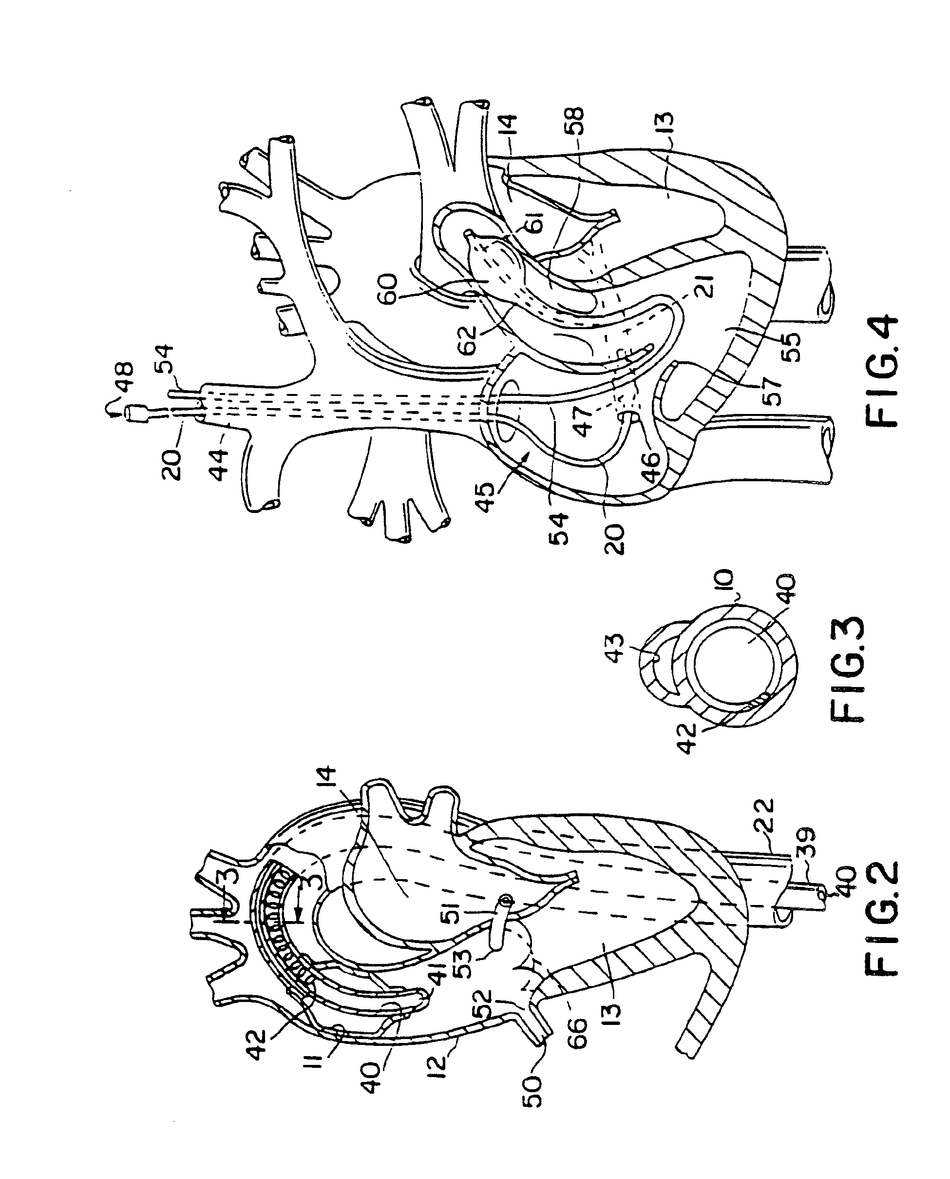
A system for accessing a patient's cardiac anatomy which includes an endovascular aortic partitioning device that separates the coronary arteries and the heart from the rest of the patient's arterial system. The endovascular device for partitioning a patient's ascending aorta comprises a flexible shaft having a distal end, a proximal end, and a first inner lumen therebetween with an opening at the distal end. The shaft may have a preshaped distal portion with a curvature generally corresponding to the curvature of the patient's aortic arch. An expandable means, e.g. a balloon, is disposed near the distal end of the shaft proximal to the opening in the first inner lumen for occluding the ascending aorta so as to block substantially all blood flow therethrough for a plurality of cardiac cycles, while the patient is supported by cardiopulmonary bypass. The endovascular aortic partitioning device may be coupled to an arterial bypass cannula for delivering oxygenated blood to the patient's arterial system. The heart muscle or myocardium is paralyzed by the retrograde delivery of a cardioplegic fluid to the myocardium through patient's coronary sinus and coronary veins, or by antegrade delivery of cardioplegic fluid through a lumen in the endovascular aortic partitioning device to infuse cardioplegic fluid into the coronary arteries. The pulmonary trunk may be vented by withdrawing liquid from the trunk through an inner lumen of an elongated catheter. The cardiac accessing system is particularly suitable for removing the aortic valve and replacing the removed valve with a prosthetic valve.

Description

FIELD OF THE INVENTIONThis invention relates generally to devices and methods for performing cardiovascular, pulmonary and neurosurgical procedures wherein the patient is placed on cardiopulmonary bypass. More specifically, the invention relates to devices and methods for isolating the heart and coronary blood vessels from the remainder of the arterial system, to facilitate arresting the heart and establishing cardiopulmonary bypass. This invention also relates to methods and systems for performing minimally-invasive cardiac procedures such as the endovascular placement of or removal and replacement of heart valves.BACKGROUND OF THE INVENTIONVarious cardiovascular, neurosurgical, pulmonary and other interventional procedures, including repair or replacement of aortic, mitral and other heart valves, repair of septal defects, pulmonary thrombectomy, coronary artery bypass grafting, angioplasty, atherectomy, treatment of aneurysms, electrophysiological mapping and ablation, and neurova...

Claims


Application Information

Patent Timeline
Patent Type & Authority Patents(United States)
IPC IPC(8): A61F2/24A61M25/10A61M25/01A61M25/06A61M25/00A61M1/36A61B17/00A61M29/02A61F2/958
CPCA61M1/3659A61F2/2427A61M1/3653A61M25/0041A61M25/0147A61M25/0152A61M25/0662A61M25/10A61B2017/00243A61B2018/00261A61M25/0032A61M25/0125A61M25/1002A61M2025/0031A61M2025/0078A61M2025/015A61M2025/0161A61M2025/028A61M2025/1047A61M2025/1052A61M2025/1077A61M2025/1095A61M2202/047A61M2205/11A61M2205/366A61M2210/125A61M2210/127A61B2018/00232A61M1/3613A61M1/3623
Inventor STEVENS, JOHN H.STERMAN, WESLEY D.GIFFORD, III, HANSON S.MACHOLD, TIMOTHY R.
Owner EDWARDS LIFESCIENCES LLC
Why Eureka
Try Eureka