Treatment of shipboard-generated oily wastewaters

Inactive Publication Date: 2006-03-28
MEMBRANE TECH & RES
View PDF16 Cites 22 Cited by
  • Summary
  • Abstract
  • Description
  • Claims
  • Application Information

AI Technical Summary

Benefits of technology

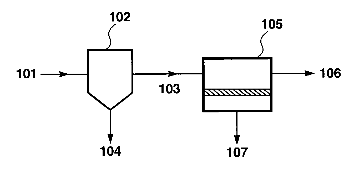
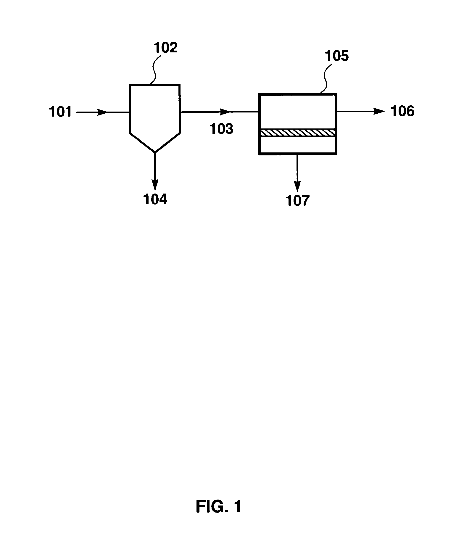
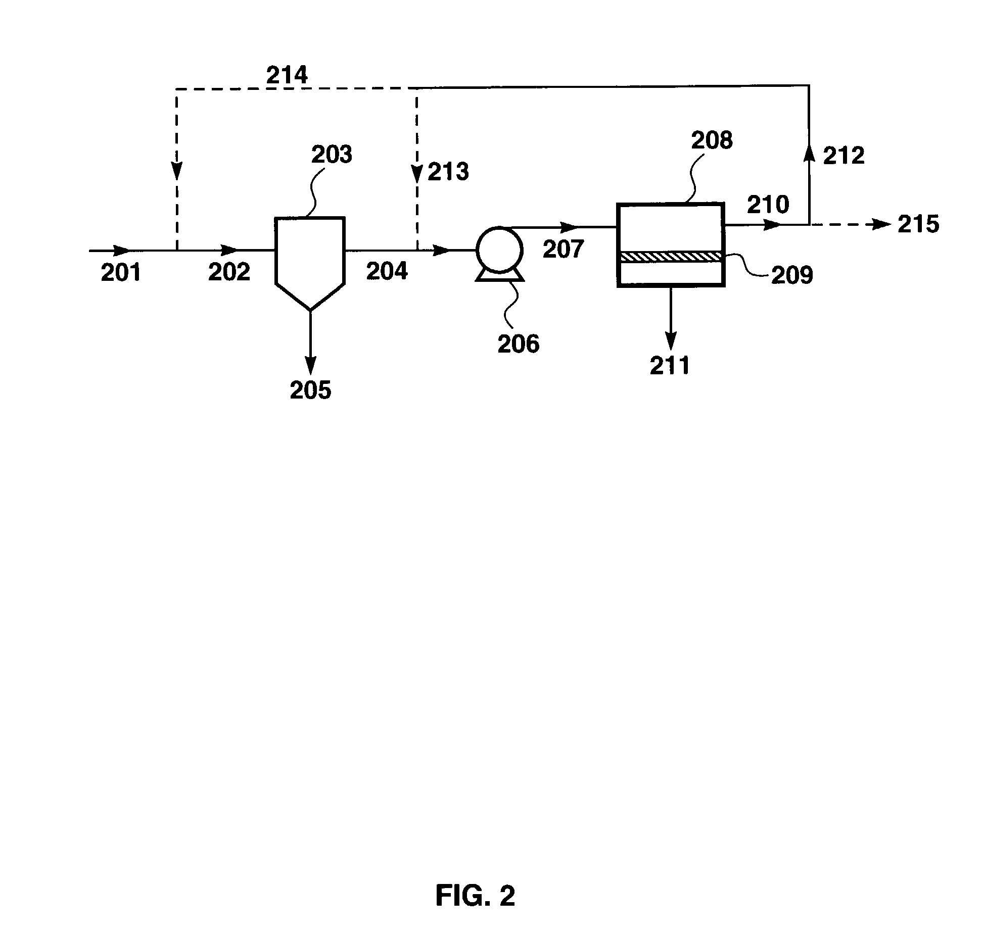
[0020]The invention is a process for separating oils from oily wastewater. The invention is particularly useful for treating oily bilge, ballast, or other wastewater generated onboard commercial and naval vessels. The separation is accomplished by the combination of a centrifugal separation step and a membrane separation step. The goal is to produce a treated water stream, preferably suitable for discharge, and to reduce the volume of the waste stream which must be subsequently treated, either onboard ship or onshore.

Problems solved by technology

Ballast water may be contaminated with oil that was transported in the ship prior to ballasting, or may contain small animal and vegetable sea life drawn in with the ballast water.
They are ineffective, however, in removing colloidal particles, emulsified oil or dissolved oil.
Since oil in these forms is usually present at least at the hundreds of ppm level, oil / water separators are unable in meet the 15 ppm limit in most cases.
Both storage and simple gravity separation obviously have many drawbacks, and a clear need for better treatment techniques exists.
However, they are very susceptible to internal fouling (plugging of pores by oil or other contaminants) and surface fouling (build-up of an oil layer on the surface of the membrane).
Cleaning gradually becomes less effective, and the transmembrane water flux may decline to a level at which more water is being generated than can be treated.
All the ultrafiltration membranes cited above are porous and are subject to severe internal and surface fouling by oil and particulate matter in the wastewater stream.
Over time, however, the pores of the membrane become permanently plugged, and the membrane must be replaced.
However, such shutdowns are inconvenient, disruptive, and costly, and the cleaning procedures may be difficult to apply and only partially effective.
Thus, such cleaning techniques are inappropriate for shipboard use.
In addition, the composition of shipboard bilge and ballast waters can vary widely during a day of ship's operation, and the membranes may be suddenly subjected to a broad range of highly-fouling oil-water emulsions, solvents, surfactants and particulates, causing erratic or unpredictable membrane performance.

Method used


Image

  • Treatment of shipboard-generated oily wastewaters
  • Treatment of shipboard-generated oily wastewaters
  • Treatment of shipboard-generated oily wastewaters

Examples


example 1

Membrane and Module Preparation

[0168]Composite membranes were made from both Pebax® 1074 and Pebax® 1647 grades (Atochem, Inc., Glen Rock, N.J.) in a two-step process. First, a microporous support layer of polyvinylidene fluoride (PVDF) was cast onto a fabric web. In the second step, the support layer was coated with the ultrathin Pebax® selective layer. After drying in an oven, a selective layer 0.5–2 μm thick was left on the support.

[0169]The selective layer thickness was determined by measuring the nitrogen flux of the composite membrane, from which the thickness of the selective layer was calculated using the known intrinsic nitrogen permeability of Pebax®. The carbon dioxide flux was also measured to ensure that the Pebax® layer was defect-free. This was done by comparing the carbon dioxide / nitrogen selectivity of the membrane with the known carbon dioxide / nitrogen selectivity of Pebax® films.

[0170]The defect-free membranes were incorporated into 2.5-inch-diameter spiral-wound ...

example 2

Permeation Properties of Modules with Model Solutions

[0172]Before beginning tests with simulated bilge water, the permeation properties of membrane modules, prepared as in Example 1, were measured with clean water and simple model solutions, using the module test system described above. During each test, the feed solution was circulated through the system at atmospheric pressure to allow the system to equilibrate. The system was pressurized only when the solute concentration in the feed had stabilized. This procedure ensured negligible accumulation of solute in the system during the tests, so that all changes in the feed composition were attributable to the membrane process.

[0173]The solute rejections of the two modules were determined with dilute aqueous solutions of magnesium sulfate, polyethylene glycol, sucrose, trichloroethylene (TCE), and toluene. The feed temperature was 25° C. and the feed pressure was 50 psig. The fluxes and solute rejections for Pebax® 1074 and Pebax®1657 ...

example 3

Comparative Example

[0176]An experiment was performed to compare the flux properties of a Pebax® 1657 composite membrane with those of a commercial ultrafiltration membrane, Membrex X-50 (Osmonics, Minnetonka, Minn.). The Pebax® membranes were prepared as in Example 1; the Membrex membranes were tested as supplied from the manufacturer. Samples of the membranes were cut into 12-cm2 stamps and were tested in a permeation test cell for 72 hours at a feed pressure of 600 psig and a feed temperature of 60° C. The feed composition was 1 wt % crude petroleum in water. FIG. 5 compares the total permeate fluxes of the two membranes as a function of operating time.

[0177]As can be seen, the initial fluxes of the commercial membrane were much higher than those of the experimental membrane. After a day of operation, however, the Pebax® membranes retained their flux properties and had marginally higher fluxes than the commercial membranes, which had suffered a flux drop of about an order of magni...


PUM

PropertyMeasurementUnit
Fractionaaaaaaaaaa
Fractionaaaaaaaaaa
Fractionaaaaaaaaaa

Abstract

A process and apparatus for treating oily wastewater, such as bilge water or ballast water, generated on a ship. The process uses a combination of a centrifugal separation step and a membrane separation step, such as an ultrafiltration step. The membrane separation step uses a dense, non-porous filtration membrane. The process is able to remove both emulsified oil and dissolved oil from the wastewater to low levels.

Description

[0001]This invention was made in part with Government support under SBIR award number 68-D-01-030, awarded by the Environmental Protection Agency. The Government has certain rights in this invention.FIELD OF THE INVENTION[0002]The invention is a process for treating shipboard-generated oily wastewater or the like. The process uses a centrifugal separation step and a membrane separation step in combination.BACKGROUND OF THE INVENTION[0003]Naval and commercial vessels generate large volumes of oily wastewater, mostly in the form of bilge water and ballast water. Bilge water typically contains various oils and fuels, grease, antifreeze, hydraulic fluids, cleaning and degreasing solvents, detergents, rags, and metals (including arsenic, copper, cadmium, chromium, lead, nickel, silver, mercury, selenium, and zinc) that collect during the daily operation of a vessel. Bilge water may also contain “gray water,” which includes galley water; turbid water from showers and laundry; and drainage...

Claims


Application Information

Patent Timeline
IPC IPC(8): B01D61/00C02F1/38B01D17/02B01D61/04B01D61/16B63B17/00C02F1/40C02F1/44
CPCB01D17/02B01D61/145B01D61/04B01D61/16B63J4/004C02F1/385C02F1/441C02F1/444B01D17/0202B01D61/025B01D17/0208B01D17/0217B01D17/085B01D2311/04C02F1/40C02F2101/32C02F2103/008Y02T70/36B01D2311/2676Y02T70/00
Inventor MAIRAL, ANURAG P.NG, ALVINWIJMANS, JOHANNES G.PINNAU, INGOLY, JENNIFER H.
Owner MEMBRANE TECH & RES
Why Eureka
Try Eureka