Intervertebral disc replacement method

a technology for intervertebral discs and replacement methods, applied in the field of electrosurgical procedures, can solve the problems of narrowing of the nerve openings in the sides of the spine, weakening of the shock absorption properties of the disc, back and leg pain, etc., and achieves the effect of reducing damage and necrosis to the underlying tissue, preventing clogging of the lumen, and removing precisely and quickly

Inactive Publication Date: 2006-09-12
ARTHROCARE
View PDF273 Cites 232 Cited by
  • Summary
  • Abstract
  • Description
  • Claims
  • Application Information

AI Technical Summary

Benefits of technology

[0023]In procedures requiring ablation of tissue, the tissue is removed by molecular dissociation or disintegration processes. In these embodiments, the high frequency voltage applied to the electrode terminal(s) is sufficient to vaporize an electrically conductive fluid (e.g., gel or saline) between the electrode terminal(s) and the tissue. Within the vaporized fluid, a ionized plasma is formed and charged particles (e.g., electrons) are accelerated towards the tissue to cause the molecular breakdown or disintegration of several cell layers of the tissue. This molecular dissociation is accompanied by the volumetric removal of the tissue. The short range of the accelerated charged particles within the plasma layer confines the molecular dissociation process to the surface layer to minimize damage and necrosis to the underlying tissue. This process can be precisely controlled to effect the volumetric removal of tissue as thin as 10 to 150 microns with minimal, heating of, or damage to, surrounding or underlying tissue structures. A more complete description of this phenomena is described in commonly assigned U.S. Pat. No. 5,683,366, the complete disclosure of which is incorporated herein by reference.
[0024]In another aspect of the invention, the present invention is useful for helping to create an operating corridor or passage between a percutaneous penetration in the patient's outer skin and a target area within the spine. Typically, this operating corridor is initially created by inserting one or more dilators through the percutaneous penetration to the target area within the spine, and then introducing a tubular retractor or similar instrument over the largest dilator. Once this is accomplished, the hollow interior of the retractor (which will serve as the operating corridor for the introduction of the necessary instruments, such as the endoscope) is typically partially filled with soft tissue, muscle and other body structures. The present invention is particularly useful for precisely and quickly removing these body structures to clear the operating corridor. To that end, an electrosurgical probe according to the invention is delivered into the hollow retractor, and one or more electrode terminal(s) are positioned adjacent to or in contact with the soft tissue or other body structures to be removed. High frequency voltage is applied between the electrode terminal(s) and one or more return electrodes such that the tissue is removed.
[0025]The tissue may be completely ablated in situ with the mechanisms described above, or the tissue may be partially ablated and partially resected and aspirated from this operating corridor. In the latter embodiment, the method of the present invention further comprises aspirating tissue fragments and fluid through an aspiration lumen in the electrosurgical instrument or another instrument. In a preferred configuration, the probe will include one or more aspiration electrode(s) at or near the distal opening of the aspiration lumen. In this embodiment, high frequency voltage is applied between the aspiration electrode(s) and one or more return electrode(s) (which can be the same or different electrodes from the ones used to ablate tissue) to partially or completely ablate the tissue fragments as they are aspirated into the lumen, thus inhibiting clogging of the lumen and expediting the tissue removal process.
[0026]The present invention offers a number of advantages over current mechanical and laser techniques for spine surgery. The ability to precisely control the volumetric removal of tissue results in a field of tissue ablation or removal that is very defined, consistent and predictable. The shallow depth of tissue heating also helps to minimize or completely eliminate damage to healthy tissue structures, cartilage, bone and / or spinal nerves that are often adjacent the target tissue. In addition, small blood vessels within the tissue are simultaneously cauterized and sealed as the tissue is removed to continuously maintain hemostasis during the procedure. This increases the surgeon's field of view, and shortens the length of the procedure. Moreover, since the present invention allows for the use of electrically conductive fluid (contrary to prior art bipolar and monopolar electrosurgery techniques), isotonic saline may be used during the procedure. Saline is the preferred medium for irrigation because it has the same concentration as the body's fluids and, therefore, is not absorbed into the body as much as other fluids.
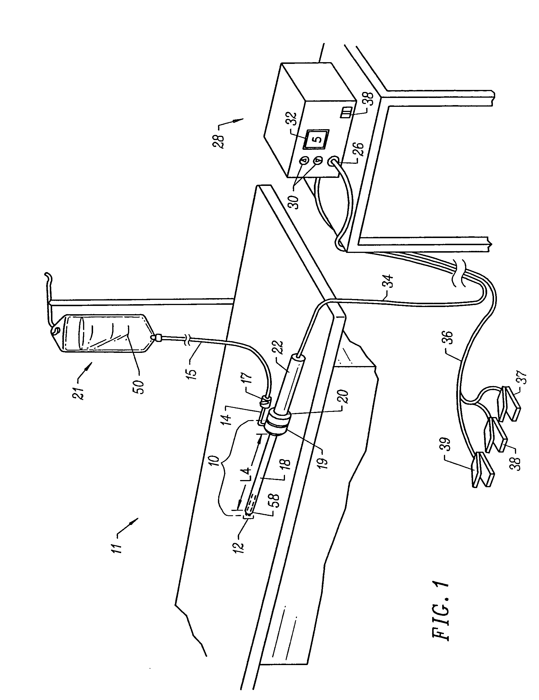
[0027]Apparatus according to the present invention generally include an electrosurgical probe or catheter having a shaft with proximal and distal ends, one or more electrode terminal(s) at the distal end and one or more connectors 
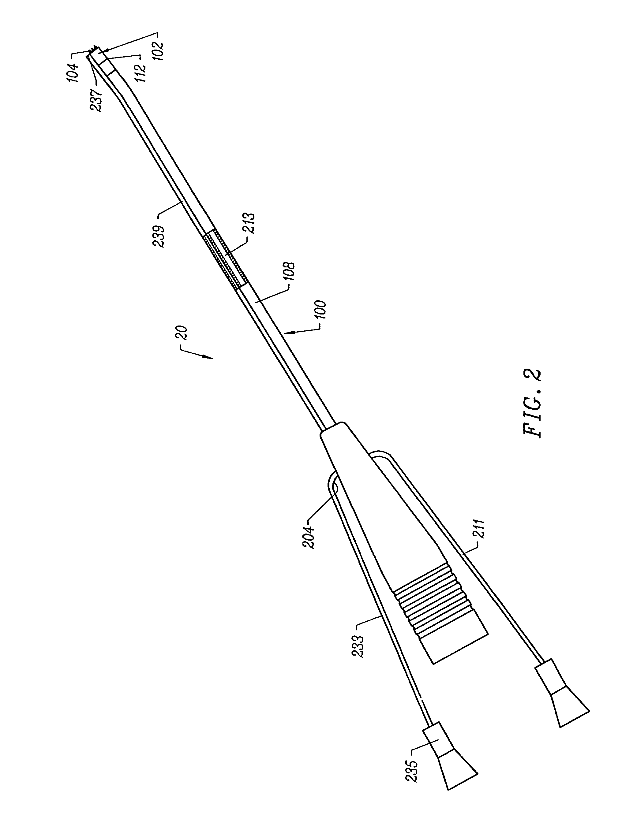
coupling the electrode terminal(s) to a source of high frequency electrical energy. For endoscopic spine surgery, the shaft will have a distal end portion sized to fit between adjacent vertebrae in the patient's spine. In some embodiments, the distal end portion is substantially planar, and it offers a low profile, to allow access to confined spaces without risking iatrogenic injury to surrounding body structures or nerves, such as vertebrae or spinal nerves. Usually, the distal end portion will have a combined height (i.e., including the active electrode(s)) of less than 2 mm and preferably less than 1 mm.
[0028]The apparatus will preferably further include a fluid delivery element for delivering electrically conducting fluid to the electrode terminal(s) and the target site. The fluid delivery element may be located on the probe, e.g., a fluid lumen or tube, or it may be part of a separate instrument. Alternatively, an electrically conducting gel or spray, such as a saline electrolyte or other conductive gel, may be applied the target site. In this embodiment, the apparatus may not have a fluid delivery element. In both embodiments, the electrically conducting fluid will preferably generate a current flow path between the electrode terminal(s) and one or more return electrode(s). In an exemplary embodiment, the return electrode is located on the probe and spaced a sufficient distance from the electrode terminal(s) to substantially avoid or minimize current shorting therebetween and to shield the return electrode from tissue at the target site.

Problems solved by technology

This results in a weakening of the shock absorption properties of the disc and a narrowing of the nerve openings in the sides of the spine which may pinch nerves.
This disc degeneration can eventually cause back and leg pain.
The mere proximity of the nucleus pulposis or a damaged annulus to a nerve can cause direct pressure against the nerve, resulting in numbness and weakness of leg muscles.
In addition, the risk of instability from ligament and bone removal is generally lower in endoscopic procedures than with open discectomy.
Unfortunately, these mechanical instruments greatly lengthen and increase the complexity of the procedure.
In addition, these instruments sever blood vessels within this tissue, usually causing profuse bleeding that obstructs the surgeon's view of the target site.
In addition to the above problems with mechanical instruments, there are serious concerns because these instruments are not precise, and it is often difficult, during the procedure, to differentiate between the target disc tissue, and other structures within the spine, such as bone, cartilage, ligaments, nerves and non-target tissue.
Unfortunately, lasers are both expensive and somewhat tedious to use in these procedures.
Another disadvantage with lasers is the difficulty in judging the depth of tissue ablation.
These monopolar devices, however, suffer from the disadvantage that the electric current will flow through undefined paths in the patient's body, thereby increasing the risk of unwanted electrical stimulation to portions of the patient's body.
This current, however, may inadvertently flow along body paths having less impedance than the defined electrical path, which will substantially increase the current flowing through these paths, possibly causing damage to or destroying surrounding tissue or neighboring peripheral nerves.
In some cases, the disc tissue is irreparably damaged, thereby necessitating removal of a portion of the disc or the entire disc to eliminate the source of inflammation and pressure.
Or, the annulus of the disc may be intact but a lack of vertebral disc height may cause complications.
For example, migration of the implant subsequent to its implantation is undesirable.
Yet, such procedures may take an undesirably long period of time to remove an optimum amount of tissue.
Furthermore, as individuals age the disc loses its water content and become relatively stiffer.
Use of mechanical means to remove a degenerated disc may result in a significant amount of remaining fibers or wisp-like tissue.
Such tissue by-product may be difficult or impossible to remove via mechanical means.
Yet another drawback with mechanical removal of degenerated disc tissue is that the cortical endplates on the vertebral bodies is easy to damage.
Use of mechanical means to remove tissue attached to the cortical endplates may cause unintended damage to that endplate.
As discussed above, conventional means to remove vertebral tissue (e.g., mechanical, chemical, laser, conventional electrosurgical) pose significant drawbacks to efficient removal of disc tissue in preparation for implant and / or prosthetic replacement of all or a portion of the vertebral disc.

Method used


Image

  • Intervertebral disc replacement method
  • Intervertebral disc replacement method
  • Intervertebral disc replacement method

Examples


Embodiment Construction

[0066]The present invention provides systems and methods for selectively applying electrical energy to a target location within or on a patient's body, particularly including tissue or other body structures in the spine. These procedures include laminectomy / disketomy procedures for treating herniated disks, decompressive laminectomy for stenosis in the lumbosacral and cervical spine, medial facetectomy, posterior lumbosacral and cervical spine fusions, treatment of scoliosis associated with vertebral disease, foraminotomies to remove the roof of the intervertebral foramina to relieve nerve root compression and anterior cervical and lumbar diskectomies. These procedures may be performed through open procedures, or using minimally invasive techniques, such as thoracoscopy, arthroscopy, laparascopy or the like.

[0067]In the present invention, high frequency (RF) electrical energy is applied to one or more electrode terminals in the presence of electrically conductive fluid to remove and...


PUM

PropertyMeasurementUnit
temperatureaaaaaaaaaa

Abstract

The present invention provides systems and methods for selectively applying electrical energy to a target location within a patient's body, particularly including tissue in the spine. The present invention applies high frequency (RF) electrical energy to one or more electrode terminals in the presence of electrically conductive fluid to contract collagen fibers within the tissue structures. In one aspect of the invention, a system and method is provided for removing a vertebral disc in preparation for implanting a prosthetic disc or removing a portion of the vertebral disc such as the nucleus pulposus in preparation for placing a prosthetic nucleus within the annulus of the disc. The present invention also teaches shrinking residual tissue in preparation for placing the implants.

Description

RELATED APPLICATIONS[0001]This application is a continuation-in-part of U.S. patent application Ser. No. 09 / 026,698 filed Feb. 20, 1998, now U.S. Pat. No. 6,620,155, which is a continuation-in-part of U.S. patent application Ser. No. 08 / 680,159 filed Jul. 16, 1996, now U.S. Pat. No. 5,902,272, the complete disclosure of each which are incorporated herein by reference for all purposes.[0002]The present invention is related to commonly assigned Provisional Patent Application Nos. 60 / 062,996 and 60 / 062,997, non-provisional U.S. patent application Ser. No. 08 / 970,239 entitled “Electrosurgical Systems and Methods for Treating the Spine”, filed Nov. 14, 1997, and Ser. No. 08 / 977,845 entitled “Systems and Methods for Electrosurgical Dermatological Treatment”, filed on Nov. 25, 1997, U.S. application Ser. No. 08 / 753,227, filed on Nov. 22, 1996, and PCT International Application, U.S. National Phase Serial No. PCT / US94 / 05168, filed on May 10, 1994, now U.S. Pat. No. 5,697,281, which was a co...

Claims


Application Information

Patent Timeline
Patent Type & Authority Patents(United States)
IPC IPC(8): A61B18/14A61B18/12A61B17/00A61B17/22A61B18/00A61B19/00A61F2/02A61M3/02A61M25/01
CPCA61B18/12A61B18/1402A61B18/148A61B18/1482A61B18/1485A61B18/149A61B18/1492A61M25/0133A61B18/1206A61M25/0158A61B18/14A61B2017/00026A61B2017/00084A61B2017/00097A61B2017/00101A61B2017/00247A61B2017/00292A61B2017/003A61B2017/22001A61B2017/22038A61B2018/00029A61B2018/00083A61B2018/00119A61B2018/0016A61B2018/00178A61B2018/00196A61B2018/00327A61B2018/00392A61B2018/00434A61B2018/00505A61B2018/00577A61B2018/00583A61B2018/00642A61B2018/0066A61B2018/00678A61B2018/00702A61B2018/00726A61B2018/00761A61B2018/00791A61B2018/00797A61B2018/00821A61B2018/00827A61B2018/00875A61B2018/00886A61B2018/1213A61B2018/124A61B2018/1253A61B2018/126A61B2018/1273A61B2018/1467A61B2018/1472A61B2018/1497A61B2018/162A61B2018/165A61B2019/5276A61B2218/002A61F2/2493A61M3/0283A61M25/0147A61B2090/378
Inventor HOVDA, DAVID C.MARTINI, BRIANCONFORTI, ZSUZSIWOLOSZKO, JEAN
Owner ARTHROCARE
Why Eureka
Try Eureka