

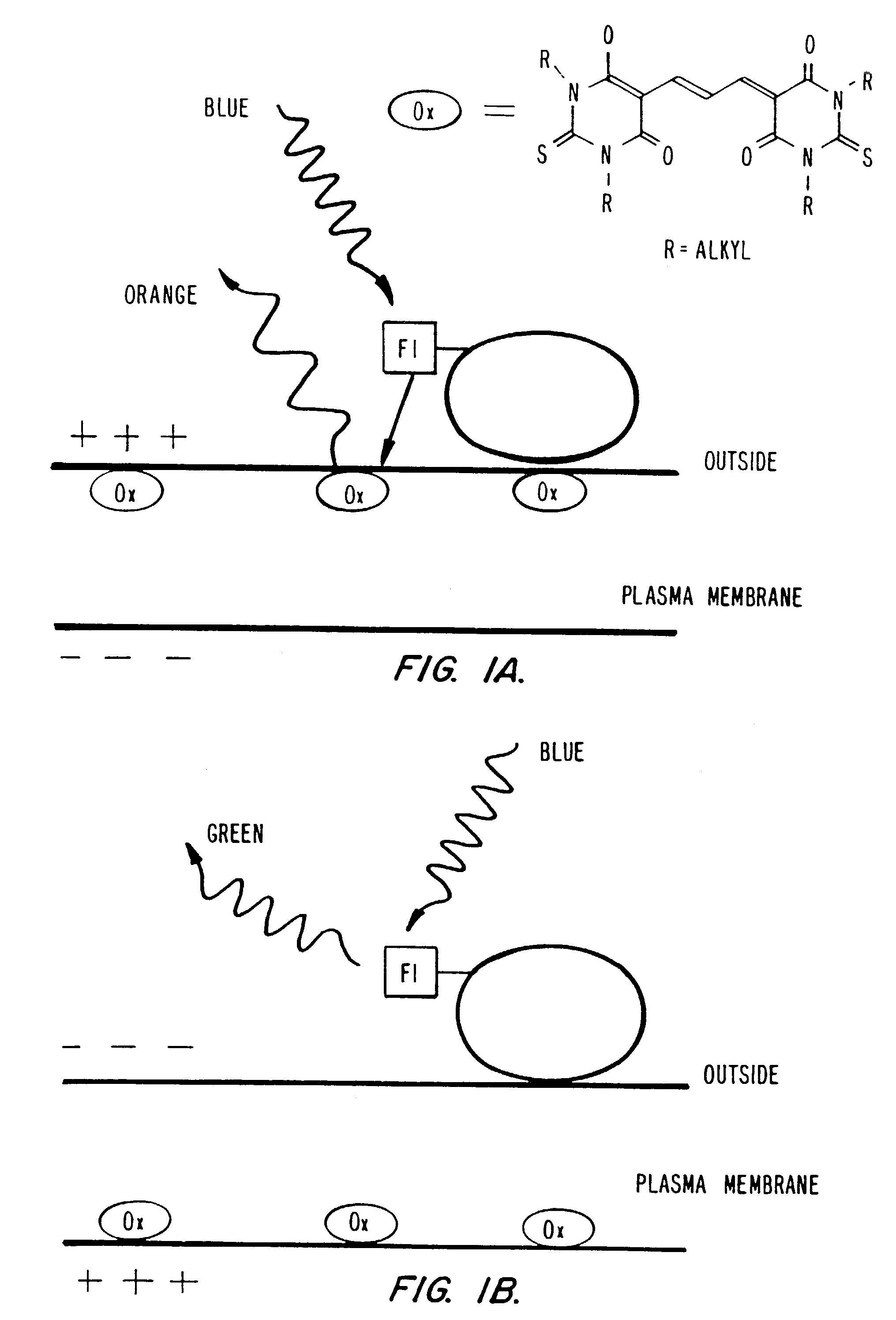
Detection of transmembrane potentials by optical methods
a transmembrane potential and optical method technology, applied in the direction of fluorescence/phosphorescence, group 3/13 element organic compounds, group 5/15 element organic compounds, etc., can solve the problem that indicators fail to give any shift in fluorescence wavelengths or ratiometric output, and their responses are slow
- Summary
- Abstract
- Description
- Claims
- Application Information
AI Technical Summary
Benefits of technology
Problems solved by technology
Method used
Image

Examples
example i
of Oxonol Dyes
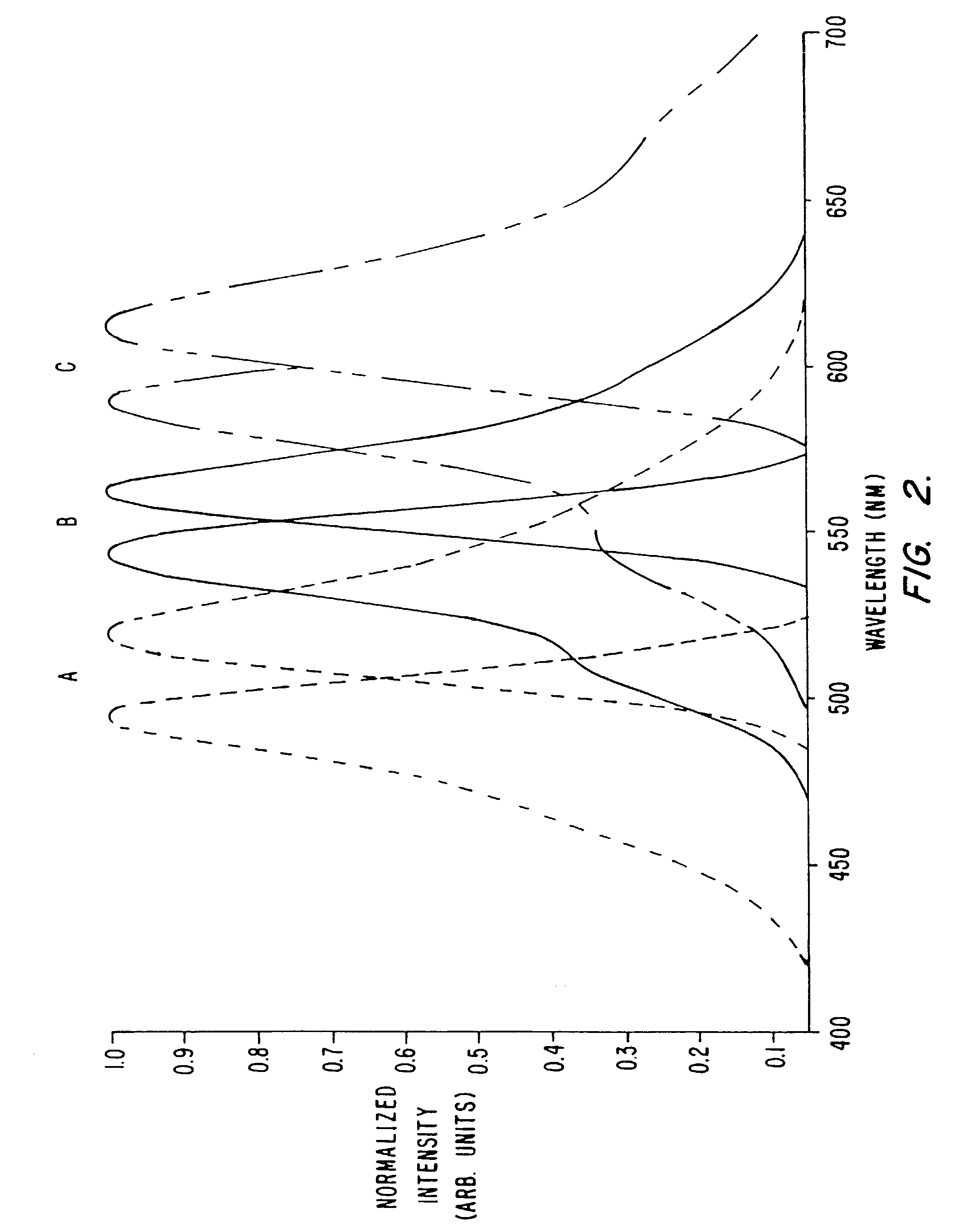
[0234]All starting materials and reagents were of the highest purity available (Aldrich; Milwaukee, Wis.) and used without further purification, except where noted. Solvents were HPLC grade (Fisher) and were dried over activated molecular sieves 3 Å. NMR spectra were acquired on a Varian Gemini 200 MHz spectrometer (Palo Alto, Calif.). The spectra were referenced relative to the residual solvent peak (CHCl3,=7.24 ppm). Fluorescence spectra were taken on a SPEX Fluorolog-2 (Edison, N.J.) and were corrected for lamp and detector wavelength variations using the manufacturer supplied correction files.
Bis-(1,3-dibutyl-2-thiobarbiturate)-trimethineoxonol DiSBA-C4-(3):
[0235]DiSBA-C4-(3) was synthesized based on the procedure for the ethyl derivative [British Patent 1,231,884]. 1,3-di-butyl-thiobarbiturate (500 mg, 2 mmol) was dissolved in 700 μL of pyridine. To this solution, a mixture of 181 μL (1.1 mmol) of malonaldehyde bis(dimethyl acetal) and 100 μL of 1 M HCl was added....
example ii
of Flourescent Phospholipids
[0239]Cou-PE: 3-amidoglycine-6-chloro-7-butyryloxy coumarin was synthesized as described in pending U.S. patent application, Ser. No. 08 / 407,554, filed Mar. 20, 1995 as set out below. For synthesis of 2,4 dihydroxy-5-chlorobenzaldehyde, 21.7 g (0.15 Mol) 4-chlororesorcinol were dissolved in 150 ml dry diethyl ether and 27 g finely powdered zinc (II) cyanide and 0.5 g potassium chloride were added with stirring. The suspension was cooled on ice. A strong stream of hydrogen chloride gas was blown into the solution with vigorous stirring. After approximately 30 minutes the reactants were dissolved. The addition of hydrogen chloride gas was continued until it stopped being absorbed in the ether solution (approx. 1 hour). During this time a precipitate formed. The suspension was stirred for one additional hour on ice. Then the solid was let to settle. The ethereal solution was poured from the solid. The solid was treated with 100 g of ice and heated to 100 deg...
example iii
f Linker for Donors and Acceptors
[0246]This example is with reference to FIGS. 14–16. 12-p-methoxybenzylthio-1-dodecanol (1): Na (800 mg, 34.8 mmol) was dissolved in 30 mL of dry MeOH. Under argon, p-methoxybenzylmercaptan (2.75 mL, 3.04 g, 19.7 mmol) was added to the methoxide solution. After a few minutes, 12-bromododecanol (2.5 g, 9.43 mmol) was dropped into the reaction mixture. Within 5 minutes a solid began to come out of solution. After a minimum of 3 h, the reaction was filtered and washed 3× with cold MeOH, yielding 2.874 g (8.49 mmol, 90%) of pure product after drying. 1H NMR (CDCl3): d 7.23 (d, J=8.8 Hz, 2H, AA′ of AA′ BB′ aromatic system), 6.85 (d, J=8.8 Hz, 2H, BB′ of AA′ BB′ aromatic system), 3.80 (s, 3H, methoxy), 3.66 (s, 2H, benzyl), 3.64 (dt, J1=6.6 Hz, J2=5.5 Hz, 2H, RCH2OH), 2.40 (t, J=7.3 Hz, 2H, RSCH2R), 1.50–1.65 (cm, 4H, CH2 b to heteroatoms), 1.2–1.4 (cm, 16H, bulk methylenes).
[0247]12-p-methoxybenzylthio-1-bromododecane (2): (1) (500 mg, 1.48 mmol) was mixe...
PUM
| Property | Measurement | Unit |
|---|---|---|
| time constant | aaaaa | aaaaa |
| time | aaaaa | aaaaa |
| time | aaaaa | aaaaa |
Abstract
Description
Claims
Application Information