Composite structures, such as coated wiring assemblies, having integral fiber optic-based condition detectors and systems which employ the same

a technology of condition detector and composite structure, applied in the field of fiber optic condition detection, can solve the problems of human error and inconsistency, difficulty in detecting ground faults and arcings, and inaccessible visual inspection, etc., and achieve the effects of enhancing the detection of tensile, bending and pinching loads, reducing the compressive strain of fiber optic sensors, and facilitating thermal compensation

Inactive Publication Date: 2006-12-26
LUNA INNOVATIONS
View PDF14 Cites 134 Cited by
  • Summary
  • Abstract
  • Description
  • Claims
  • Application Information

AI Technical Summary

Benefits of technology

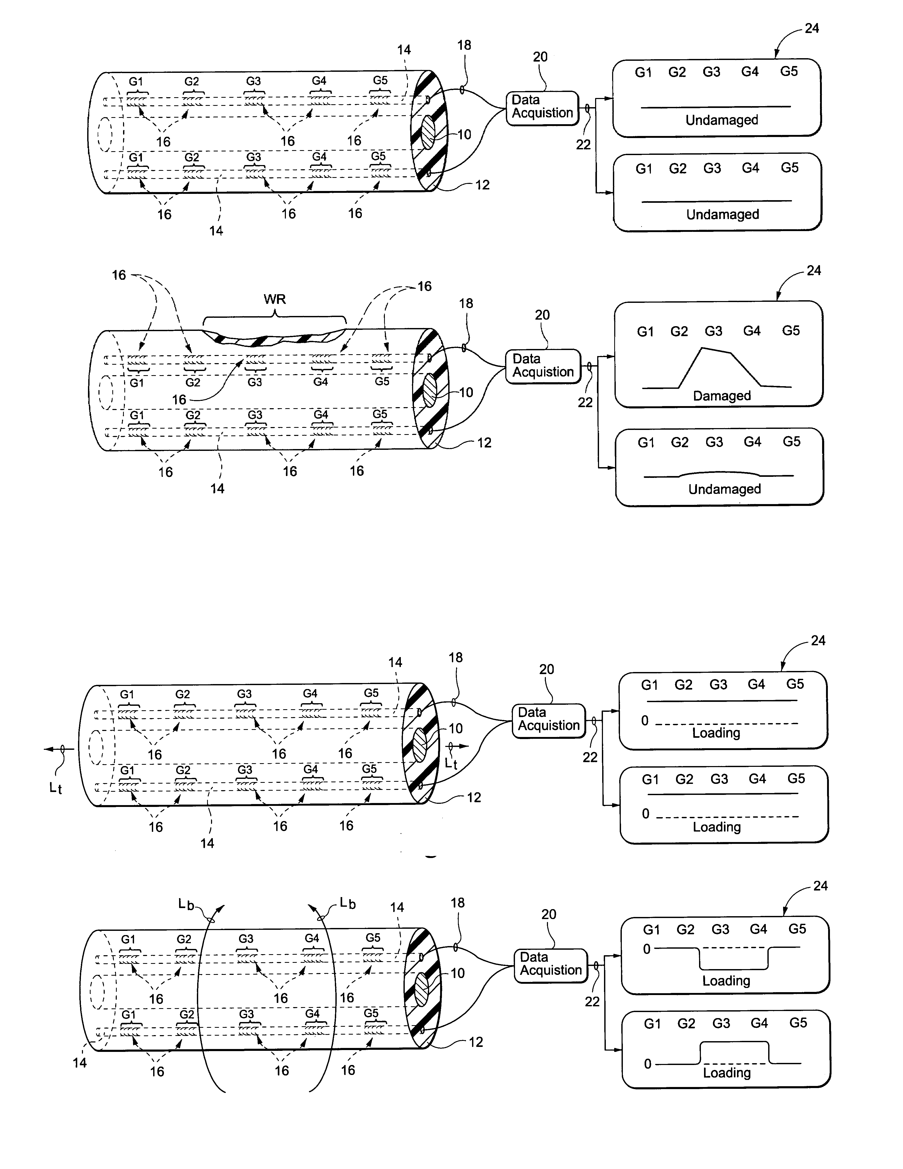
[0014]The magnitude of the compressive strain in the fiber optic sensor decreases as the coating is worn away. Measured strains in the Bragg grating may thus be used in accordance with the present invention so as to monitor the progression of the wear processes. In such embodiments, the optical fiber sensors could thereby function as wear sensors capable of being multiplexed using a number of known art techniques, including optical frequency domain reflectometry.
[0015]The complete sensor system may therefore include multiple optical sensor fibers that are functionalized to detect or have varying sensitivities to residual in

Problems solved by technology

Ground faults and arcing are difficult to detect because these condition often are intermittent and occur only during operational conditions.
However, often damaged wiring is hidden and not accessible for visual inspection.
Manual inspection has a number of other drawbacks, including human error and inconsistency, accessibility, cost and infrequent inspection intervals and time required for inspection.
Also, in many cases further damage of wiring systems is caused by these manual maintenance and inspection activities.
However, such a prior proposal necessarily depends on the damage to and actual severing of the sensing element.
It is known, however, that damage to electrical systems may be due to high temperature transients, tension, bending, pinch points and chemical contamination.
The prior proposal does not provide for the detection of t

Method used


Image

  • Composite structures, such as coated wiring assemblies, having integral fiber optic-based condition detectors and systems which employ the same
  • Composite structures, such as coated wiring assemblies, having integral fiber optic-based condition detectors and systems which employ the same
  • Composite structures, such as coated wiring assemblies, having integral fiber optic-based condition detectors and systems which employ the same

Examples


example 1

[0064]Residual stresses were produced between an insulating polyolefin tube and an optical fiber sensor. Wire insulation was simulated by semi-rigid adhesively lined polyolefin heat shrink tubing (3M Corporation). Initial wire insulation tests were conducted using the FiberPro™ system (Luna Innovations) to monitor single optical fiber Bragg gratings. The fiber was cleaned with isopropyl alcohol and then a thin coating of cyanoacrylate adhesive was applied to promote adhesion between the fiber and the polyolefin tubing. The fiber grating was then placed into the adhesively lined polyolefin tubing. A heat gun was used to shrink the tubing and melt the thermoplastic adhesive lining. At the peak temperature, the tubing was compressed to push entrapped air out of the tube and fully wet the fiber with the thermoplastic adhesive. The Bragg grating reflected peak position was continually monitored with the FiberPro system during the application and cooling of the polyolefin tubing.

[0065]The...

example 2

[0066]Residual stresses were produced between a polymer coating and an optical fiber sensor. Coatings were prepared using a polymer matrix containing a range of particulate additives including TERFENOL-D powder from Etrema Products, Inc. and iron fines. The particulate were approximately 25% volume fraction of the coating system. The TERFENOL-D powder particle sizes were less than 300 μm. The iron powder had a particle size less than 40 mesh (425 μm).

[0067]Optical fiber sensors including Bragg gratings (commercially available from Luna Innovations, Inc.) were coated with Spurr Low-Viscosity Embedding Media a four-part epoxy from Polysciences, Inc. This epoxy was used as the matrix material for these coatings. The approximately 2 mm thick coatings were cured at 70° C. for 16 hours. The total change in the reflected wavelengths of the coated optical fiber sensors were recorded for the four part epoxy with iron fines and TERFANOL-D particles. The reflected wavelength decreased by 1.5 t...

example 3

[0068]Wear tests were performed by mounting the polyolefin tube and Bragg sensor assembly described in Example 1 in a metallographic epoxy mount which was cast in a cylindrical mold. A V-shaped groove was machined into the mount and the fiber Bragg grating in the polyolefin tube was placed into the groove. A five minute epoxy was used to fill in the groove around the damage sensor. Silicon carbide 180 grit abrasive paper was used to generate flat parallel surfaces on both ends of the metallographic mount. All grinding was performed using deionized water as a lubricant to minimize heating of the sample. The face of the mount containing the insulation damage sensor was ground down to expose the polyolefin tube. Digital calipers were used to measure the thickness of the mount. To minimize temperature effects, the mount was placed in 500 ml of deionized water at room temperature. Once the mount equilibrated with the water temperature, the reflected Bragg peak position (wavelength) was r...


PUM


Abstract

Integral fiber optic-based condition sensors detect conditions of a composite structure, e.g., a coated wire assembly so as to detect damage or conditions that may damage the same. Preferably, at least one optical fiber sensor having a plurality of Bragg gratings written into the fiber at spaced-apart locations along its axial length is integrated into the electrical insulator coating of a wire, wire bundle or wiring harness. The fiber optic sensor may thus be employed to measure the environmental loads on the electrical wiring including stresses from bending, axial loading, pinch points, high temperature excursions and chemical damage. The system is capable of detecting and locating transient conditions that might cause damage to a wiring system or permanent changes in state associated with damage events. The residual stress in the electrical insulator coating of a wire, wire bundle, or wiring harness are used to monitor the evolution of damage by wear or chaffing processes. Detected stress relief on one or more Bragg gratings will thus be indicative of damage to the insulator coating on the conductor. As such, the magnitude of such stress relief may be detected and used as an alert that the wire insulation is damaged to an unsafe extent.

Description

CROSS-REFERENCE TO RELATED APPLICATION[0001]This application is based upon, and claims domestic priority benefits under 35 USC §119(e) from, U.S. Provisional Application Ser. No. 60 / 428,908 filed on Nov. 26, 2002, the entire content of which is expressly incorporated hereinto by reference.[0002]This invention was made with Government support under Contract No. F33615-02-M-2251 awarded by the United States Air Force. The Government has certain rights in the invention.FIELD OF THE INVENTION[0003]The present invention relates generally to fiber optic condition detection. In especially preferred embodiments, the present invention relates to the detection of damage and / or conditions that may lead to damage in wiring systems. The fiber optic detection provides for the temporal and spatial location of damage or damaging conditions in a wiring system. In preferred forms, the invention is embodied in, and thereby relates to, wiring systems having integral fiber optic-based integrity sensors ...

Claims


Application Information

Patent Timeline
IPC IPC(8): G01J1/42G01J1/04G01J5/08
CPCG01B11/18G01M11/086G02B6/022G02B6/02204D07B1/145D07B2301/5577
Inventor FRIEDERSDORF, FRITZWAVERING, THOMAS A.
Owner LUNA INNOVATIONS
Why Eureka
Try Eureka