Apparatus and method for luminometric assay

a luminometric assay and apparatus technology, applied in the field of apparatus and system for dna detection, can solve the problems of difficult significant obstacle in the optical system relating to the excitation light source, and achieve the effect of significantly simplifying the optical system, reducing the cost of miniaturization and cost reduction, and strengthening the optical coupling between a sample and an optical sensor

Inactive Publication Date: 2007-01-16
HITACHI LTD
View PDF10 Cites 39 Cited by
  • Summary
  • Abstract
  • Description
  • Claims
  • Application Information

AI Technical Summary

Benefits of technology

[0010]For a DNA testing system for medical diagnosis, it is required that (1) a small amount sample is required and the cost of reagents is low, (2) simultaneous testing of a plurality of DNA sites is possible, (3) mutation of 1 nucleotide can be distinguished and detected, and (4) a signal detection apparatus be small-size and low-cost.
[0011]In a detection system using DNA microarrays that can test a large number of sites, fluorescence analysis is commonly used. Thus, the signal detection part thereof comprises an excitation light source such as a laser or halogen lamp, a fluorescence detection part, an optical system and a moving mechanism of a sample stage. However, the optical system relating to the excitation light source is a significant obstacle to miniaturization of the detection part. A detection method using chemiluminescence, such as the previously proposed pyrosequence technique or BAMPER (bioluminometric assay with modified primer extension reactions) technique (Nucleic Acid Research vol. 29, e93 (2001)) or the like, does not require a light source for excitation, and thus enables miniaturization of a detection part. For example, the flow of detection of SNPs using BAMPER is shown in FIG. 2. A wildtype probe DNA 302 and a mutant probe DNA 304 are hybridized to a target 301, and depending on whether the target is a wildtype or a mutant, complementary strand syntheses is allowed to proceed 303 or not proceed (or the reverse thereof). Inorganic pyrophosphate 307 generated along with synthesis of the complementary strand is converted to ATP, and by the reaction thereof with luciferin, chemiluminescence is obtained and determined. Although this is an extremely simple and easy method, as in the conventional method, high sensitivity is required for the detector. As a signal detection means, a photomultiplier tube or cooled CCD (charge coupled device) are already widely used, however it has been difficult to carry out miniaturization and cost reduction while maintaining high sensitivity. Moreover, in the conventional signal detection method, to accurately determine a slight difference in signal intensity between two samples it has been necessary to use a procedure that separately measures each of the signals and then compares the measurement values. To solve these problems, there is a need for a novel method and assay system that can perform high sensitivity measurement of the signals of two samples simply and quickly. Further, to realize assaying with high throughput by simultaneous measurement of a plurality of items, there is a need for a structure that enables simple processing of a large number of assay items or samples at the same time.
[0012]As a means for solving these problems, the present invention characteristically embodies (1) a structure in which a light-sensitive detector comprises a photodiode array to efficiently capture luminescence from a plurality of samples, wherein each of the biological samples is brought into a one-to-one correspondence with a pixel of the light-sensitive detector, and the detector is disposed appressed against a sample plate, (2), a mechanism comprising 2 or more decoders as pixel addressing means for addressing an arbitrary pixel to conduct differential amplification of output in order to accurately determine faint luminescence emitted from a sample, wherein the mechanism simultaneously detects a signal from a sample of interest and a signal from a control sample and conducts differential amplification of the detected signals, (3) a mechanism that carries out reaction with differing probes by a single dispensing of a sample, by providing as subcells a plurality of small sections in each reaction bath on a sample plate to which a sample is added, to realize fast determination of a small amount of sample.
[0014]In contrast to the above, because an assay method using chemiluminescence does not require excitation light, the optical system can be significantly simplified and, moreover, the optical sensor and sample can be brought into close proximity with each other. Examples of assay methods using chemiluminescence include the BAMPER technique. In BAMPER, probe DNA is hybridized to a target and depending on whether the target is a wildtype or mutant, complementary strand synthesis is allowed to proceed or not proceed (or the reverse thereof). Inorganic pyrophosphate generated in the case where complementary strand synthesis has occurred is converted to ATP, and this is reacted with luciferin to obtain chemiluminescence, which is then measured. In the present invention, an optical sensor array comprising a plurality of optical sensors is used, and the sample plate and optical sensor array substrate are fixed together such that the reaction baths and pixels of the optical sensor array correspond one-to-one in the vertical direction. According to the present invention, there is provided a structure that reads light generated in a reaction bath appressed thereto by means of the optical sensor of the pixel that has been selected. Thus, a moving mechanism of a sample plate or optical system becomes unnecessary, and the apparatus is significantly simplified. Further, optical coupling between a sample and optical sensor is strengthened, thus enabling enhancement of detection sensitivity.
[0015]Using an optical sensor array comprising a plurality of optical sensors, by amplifying the difference in luminescence from a sample of interest and from a control sample it is possible to significantly enhance the effectual measurement sensitivity. In genetic testing by means of chemiluminescence, highly precise detection of minute variations among samples is required. Therefore, a feature is herein disclosed that simultaneously selects a sample pixel at an arbitrary location on a sample plate and a control pixel, and performs differential amplification of the signals of the two pixels. Using an optical sensor array provided with 2 independent decoders, comprising a decoder (referred to as “S-decoder ”) that selects a pixel to detect a signal of a sample of interest and a decoder (referred to as “C-decoder ”) that selects a pixel to detect a signal of a control sample, a signal from the pixel corresponding to the sample of interest and a signal from the pixel corresponding to the control sample are output to respectively independent signal lines. Thus, an offset factor that is common among the selected cells can be cancelled to enable amplification of high amplitude, thereby enabling enhancement of the detection sensitivity of faint light. While BAMPER is an extremely simple and easy method, because each site is determined independently when assaying a large number of DNA sites, improvement to facilitate labor saving is required. Specifically, it is necessary to enable simple and easy testing of various probe regions at the same time. In order to solve this problem, the present invention provides a system in which a plurality of small sub-reaction baths are provided in a reaction bath to perform determination of each one of various DNA sites of interest. Although hybridization reaction is conducted in one operation, the present invention realizes a system in which complementary strand synthesis reaction and luminescence reaction caused by a plurality of reactions are performed simultaneously, but are nevertheless distinguished from each. A different probe or target is retained in each subcell, and following hybridization of the target or probe complementary strand synthesis reaction proceeds. The complementary strand synthesis reaction is carried out in each cell in an almost isolated state. To that end, the constitution and conditions employed are such that a reaction solution of complementary strand synthesis and the accompanying chemiluminescence does not leak to outside the cell. If inorganic pyrophosphate (PPi) produced as a byproduct of complementary strand synthesis reaction flows into a different cell, it is impossible to know where the complementary strand synthesis occurred, that is, whether or not a target was present. When hybridizing a target, the solution containing the target can flow freely among all of the cells. However, after hybridization, complementary strand synthesis is carried out with each subcell in an isolated state. This is achieved by adhering a separating plate to the top part of the subcells. Chemiluminescence from the respective subcells is distinguished and detected, to simultaneously perform assay of a plurality of DNA sites.

Problems solved by technology

However, the optical system relating to the excitation light source is a significant obstacle to miniaturization of the detection part.
As a signal detection means, a photomultiplier tube or cooled CCD (charge coupled device) are already widely used, however it has been difficult to carry out miniaturization and cost reduction while maintaining high sensitivity.

Method used


Image

  • Apparatus and method for luminometric assay
  • Apparatus and method for luminometric assay
  • Apparatus and method for luminometric assay

Examples


example 1

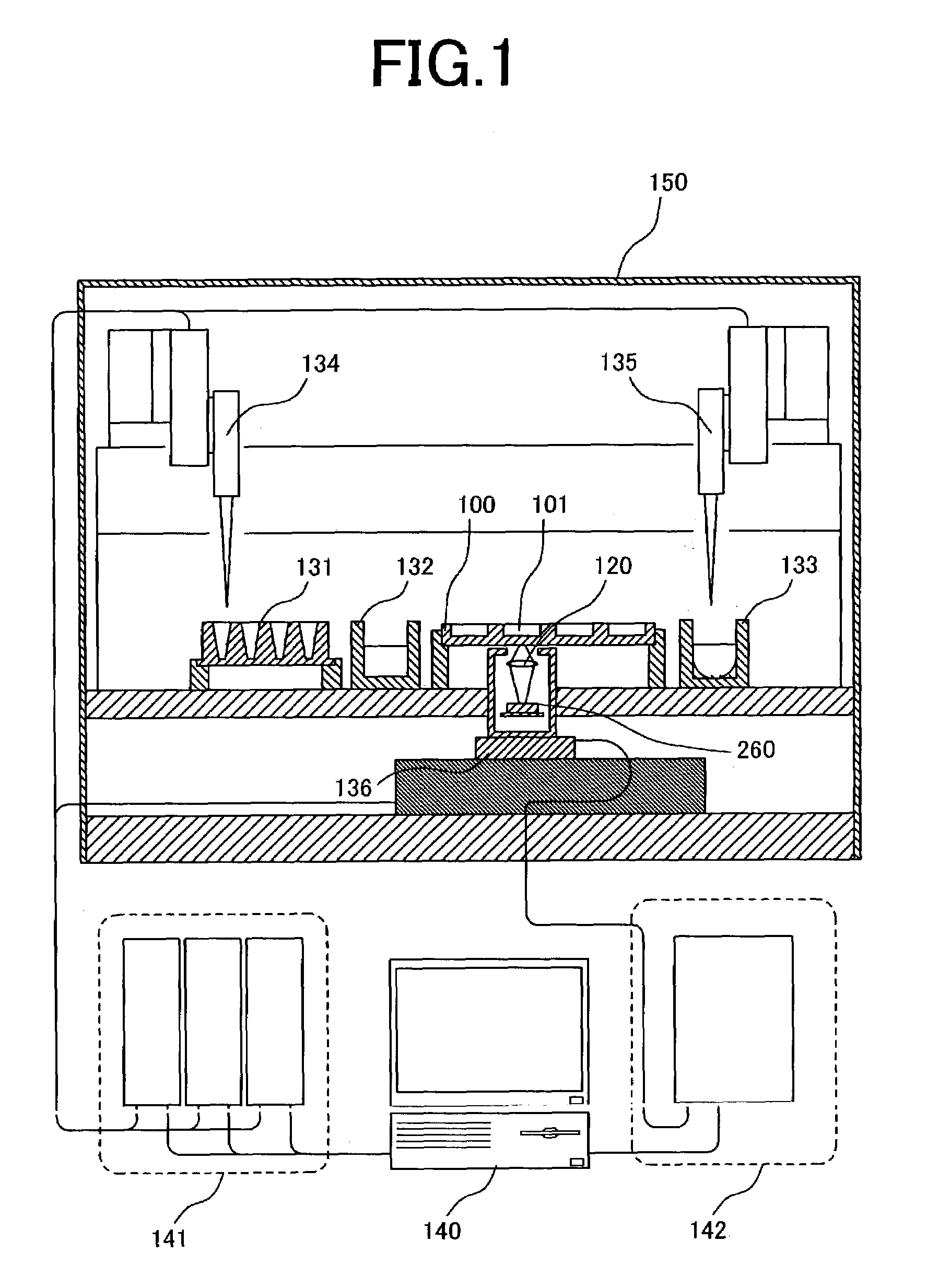
[0044]FIG. 3A is a cross-sectional view of a sample plate and optical sensor array illustrating an example of the present invention. A plurality of reaction baths and pixels are brought into a one-to-one correspondence and disposed in close proximity to each other. Here, a sample plate 100 comprises a plurality of reaction baths (2 mm in diameter, 2 mm in depth) 101a–c on a glass substrate. The bottom surface of the reaction baths is transparent, and a part of the light emitted from a sample arrives at an optical sensor array disposed underneath the sample plate. An optical sensor array 200 is composed of photodiodes 210a–c formed on a silicon substrate. Here, the positional relationship between the photodiodes and reaction baths is important. In conventional DNA assay apparatus, determination by fluorescence labelling is mainly utilized, and thus excitation light is required. Since the fluorescence, which is the signal, is faint in comparison with the intensity of the excitation li...

example 2

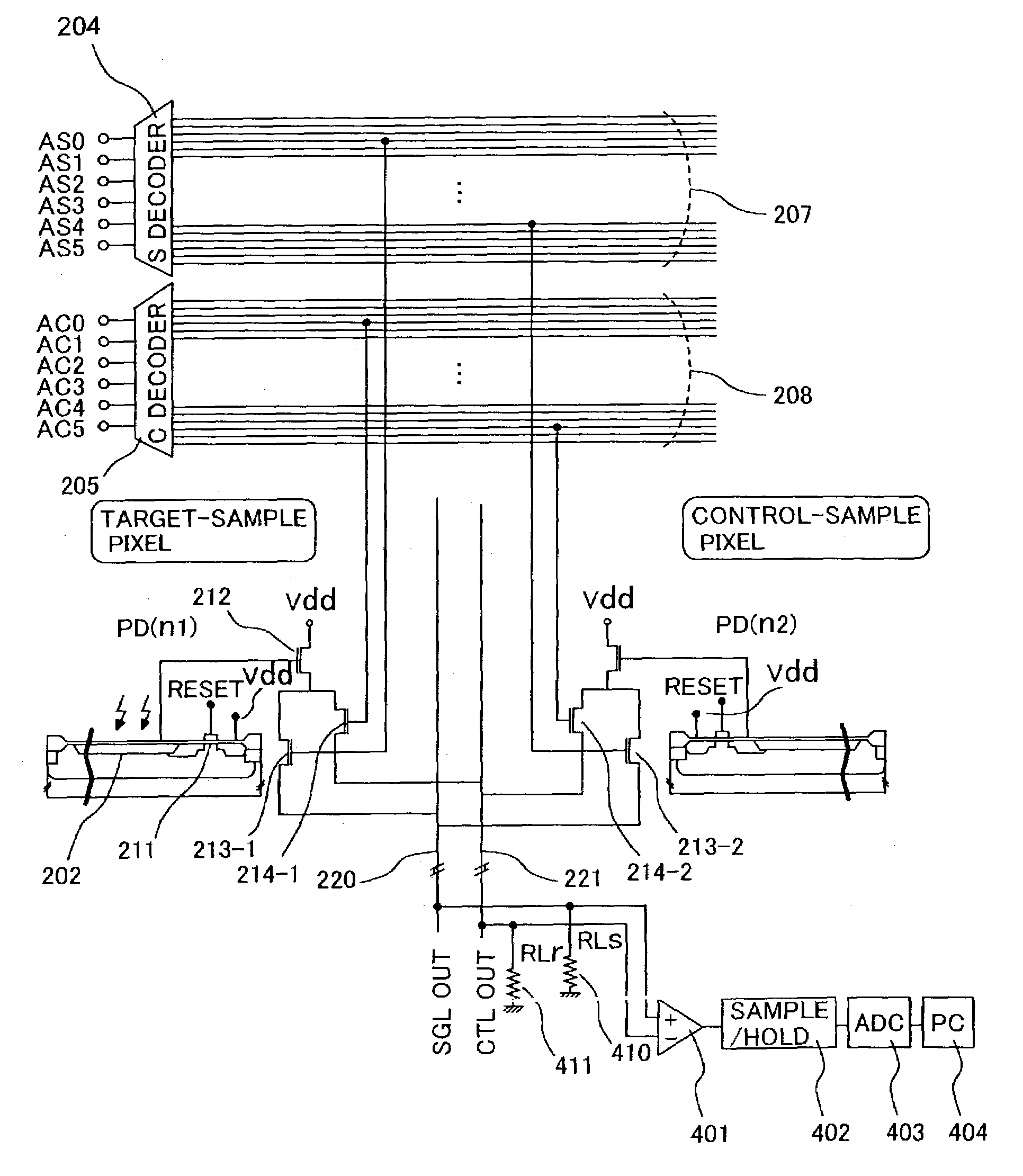
[0048]FIG. 3B shows a block diagram of an optical sensor array comprising 2 pixel-addressing circuits. FIGS. 7A to 7C show the circuitry diagram of the optical sensor array. Taking a photosensitive part 202 and a mechanism for resetting the photosensitive part and forwarding signals as 1 unit 210 (hereafter, referred to as “pixel”), a plurality of pixels is arranged on the same silicon substrate. The array shown in FIG. 3B comprises 36 pixels, wherein each pixel comprises a photodiode 202, a metal oxide semiconductor (hereafter, referred to as “MOS”) transistor for reset 211, an MOS transistor for readout 212, and MOS transistors for pixel selection 213 and 214. Each pixel is independently selected by means of a decoder for target pixel selection (S-decoder) 204 or a decoder for control pixel selection (C-decoder) 205, and a signal is output to output terminals 207 and 208 corresponding to the respective decoders.

[0049]Conventionally, a shift register has been mainly used as a means...

example 3

[0053]FIG. 11A shows an example of the configuration of a part in which a signal is output by way of output lines 220 and 221 corresponding to the decoder for selection of a target pixel (S-decoder) 204 and the decoder for selection of a control pixel. Current sources 412 and 413 are connected to output line for a target pixel signal 220 and output line for a control pixel signal 221, respectively, and, for example, current is initially set to 2 mA. The two output lines are connected to an input terminal of a differential amplifier 401, the output of the differential amplifier is connected to a sample / hold circuit, and the output thereof is read into a control computer 404 via an AD converter 403. Prior to measuring luminescence from a target sample, a target-sample and control-sample are measured at the same time in a state where the target-sample is not allowed to emit luminescence, for example in a state where luciferin, the luminescence substrate, is not added thereto, and the s...


PUM

PropertyMeasurementUnit
distanceaaaaaaaaaa
diameteraaaaaaaaaa
resistivityaaaaaaaaaa

Abstract

A small sized, cost-effective genetic testing apparatus that provides high sensitivity testing, for performing genetic testing simply and at low cost. An optical sensor array for the apparatus and method for luminometric assay comprises a means that simultaneously selects 2 pixels and detects minute amounts of chemiluminescence by obtaining the differential output of the respective signals.

Description

BACKGROUND OF THE INVENTION[0001]1. Field of the Invention[0002]The present invention relates to an apparatus and system for DNA detection such as detection of single nucleotide mutations, gene diagnosis, genetic typing or detecting biological substances such as protein and ATP.[0003]2. Description of the Related Art[0004]Analysis of the human genome sequence is almost completed, and activity is increasing in efforts to put genetic information to practical use in the medical field in areas such as diagnosis. Following the analysis of the genome sequence, gene expression profile analysis and analysis of single nucleotide polymorphisms (SNPs) in genes are now attracting attention. By examining genes expressing under a variety of conditions and investigating gene mutations of a variety of solid bodies, genetic functions and the relation between genes and disease or genes and sensitivity to pharmaceuticals can be investigated. Further, the diagnosis of disease and the like is now being ...

Claims


Application Information

Patent Timeline
Patent Type & Authority Patents(United States)
IPC IPC(8): C12M1/34C12M1/00G01N33/53C12N15/09C12Q1/68G01N21/78G01N37/00G06K9/00
CPCC12Q1/6825C12Q1/6827Y10S435/808C12Q2565/607C12Q2565/501C12Q2565/301
Inventor YAZAWA, YOSHIAKIKAMBARA, HIDEKIKAMAHORI, MASAOHARADA, KUNIOOKANO, KAZUNORI
Owner HITACHI LTD
Why Eureka
Try Eureka