High surface area cathode for electrolytic capacitors using conductive polymer

Active Publication Date: 2007-01-30
PACESETTER INC
View PDF19 Cites 49 Cited by
  • Summary
  • Abstract
  • Description
  • Claims
  • Application Information

AI Technical Summary

Benefits of technology

[0014]According to the present invention, the increased surface area of the coated cathode results in lower gas generation and, therefore, reduced capacitor swelling, reduced oxide buildup on the cathode and prevention of electrolysis. The pre

Problems solved by technology

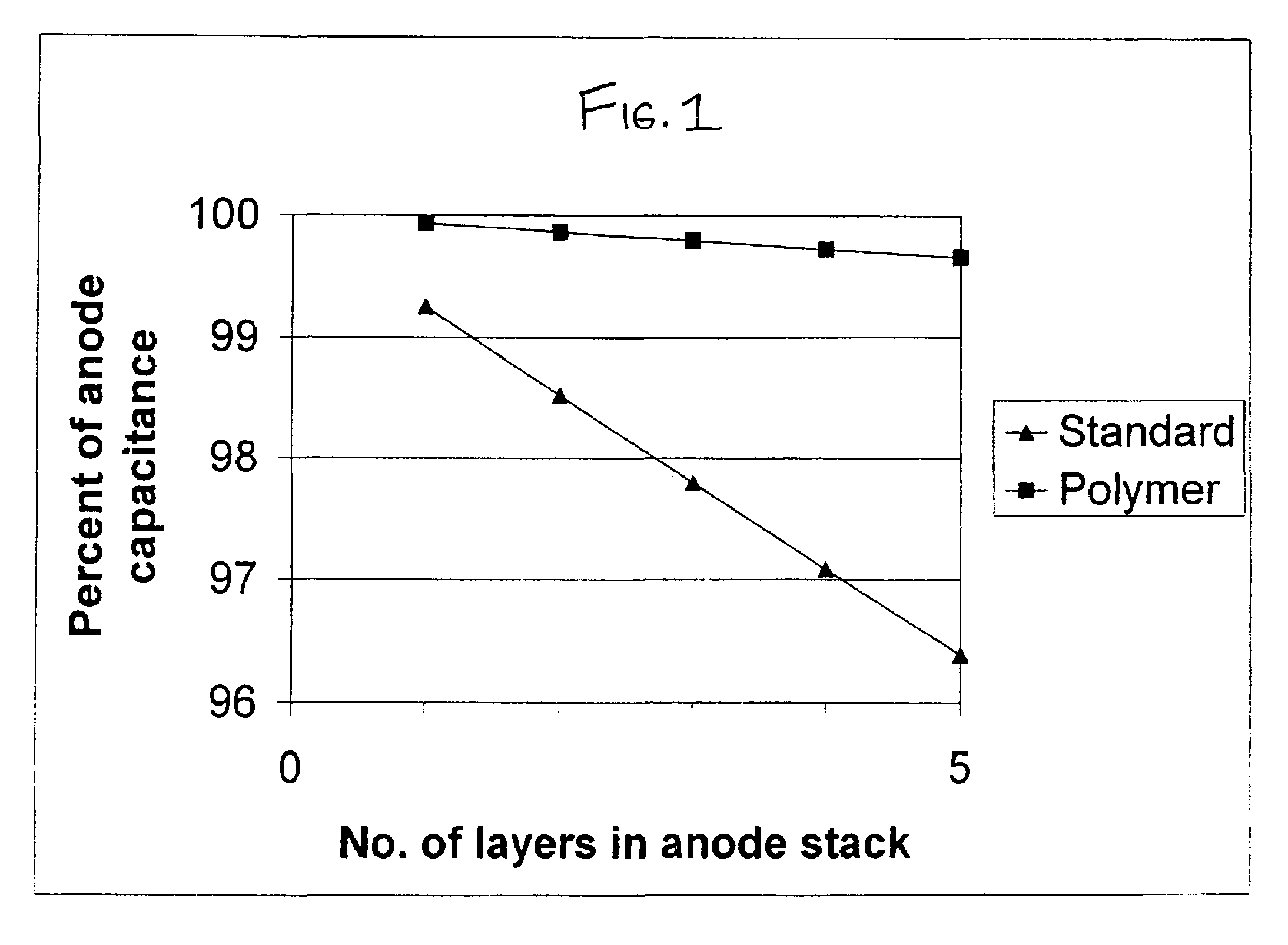
However, due to the higher capacitance values achieved with multiple anodes, traditional chemically etched aluminum cathodes provide insufficient capacitance coverage at the desired thickness (30 microns or less).
If the cathode develops a positive potential, several undesirable effects can occur: (1) during a pulse discharge operation, a significant overvoltage can be fed back to the cathode, resulting in oxide buildup on the cathode which reduces the ca

Method used


Image

  • High surface area cathode for electrolytic capacitors using conductive polymer

Examples


example 1

[0040]Titanium foil was cut into 4 cm2 samples and cleaned in a 5% oxalic acid solution at 90° C. for two minutes. A 100 ml solution was prepared of 0.5 M 3,4 ethylenedioxythiophene (EDOT) and 0.1 M tetraethylammonium tetrafluoroborate in acetonitrile.

[0041]The titanium foils were exposed to the solution at room temperature at varying current densities and times, as shown in Table 1 below, and the capacitance and ESR were observed.

[0042]

TABLE 1Current DensityExposure timeCapacitance(mA / cm2)(min)(mF)ESR (Ω)0.8058.433.81621.25513.863.61881.60518.13.91041.75812.053.80881.60811.953.8909

example 2

[0043]A coating solution was prepared with 0.13 M 3,4 ethylenedioxythiophene, 0.026 M tetraethylammonium tetrafluoroborate and 0.08 M lithium perchlorate (LiClO4) in 150 ml acetonitrile.

[0044]Titanium foil samples of 4 cm2 size were exposed to the solution while nitrogen was bubbled. Two current densities were examined. In the first experiment, a galvanic square wave was applied with the following set points: 1 mA (0.25 mA / cm2) for 120 sec, 2 mA (0.5 mA / cm2) for 420 sec and 1 mA (0.25 mA / cm2) for 60 sec. Three cycles were performed. In the second experiment, the foil was exposed to a 2 mA (0.5 mA / cm2) current for 15 minutes. After both treatments were complete, capacitance and ESR were observed on the foils (a) initially, (b) after an acetone rinse followed by a methanol rinse and one hour oven dry, and (c) after a two day air dry, as shown in Table 2 below.

[0045]

TABLE 2CapacitanceTreatmentTime Measured(mF)ESR (Ω)Galvanic SquareInitial9.153.9475WaveGalvanic SquareAfter rinse and6.37...

example 3

[0047]In a further experiment, the coating solution of Example 2 was used to coat additional 4 cm2 titanium foil samples. Varying current densities and exposure times were examined and capacitance and ESR values were obtained immediately after coating and after rinses with acetone and methanol and a 60 minute oven dry, as shown in Table 3A below. Nitrogen was bubbled during coating.

[0048]

TABLE 3ACurrentDensityExposureCapacitance(mA / cm2)Time (min)Measurement(mF)ESR (Ω)0.510Initial10.96.38800.510After rinse and8.236.202160 min. ovendry0.515Initial13.55.77300.515After rinse and10.925.845460 min. ovendry1.010Initial12.26.58441.010After rinse and11.06.267060 min. ovendry1.015Initial15.05.91701.015After rinse and10.695.903260 min. ovendry1.510Initial15.46.67581.510After rinse and13.45.800060 min. ovendry1.515Initial13.86.73711.515After rinse and10.356.014860 min. ovendry

[0049]The polymer cathode samples from Examples 2 and 3 were stored in a 65° C. oven for five days. After storage, the c...


PUM

PropertyMeasurementUnit
Percent by massaaaaaaaaaa

Abstract

The present invention is directed to a conductive polyethylenedioxythiophene (PEDOT) polymer coated electrode adapted for use as a cathode electrode of an electrolytic capacitor and a method of manufacturing the same. According to the present invention, a metal foil substrate is placed in an aqueous solution of a doped 3,4-ethylenedioxythiophene (EDOT) monomer and a co-solvent, to dissolve the EDOT monomer, and a current is applied until the desired thickness of the polymer coating is electrochemically deposited. Additionally, an organic acid is added to the aqueous solution to act as an oxidizer. In order to improve the uniformity and adherence of the coating a surfactant may also be added. In a preferred embodiment, the EDOT monomer and cosolvent are first mixed, and then added to a water solution of oxidizer and dopant. The polymer film is deposited electrochemically onto the substrate by applying a DC current between 0.05 mA/cm2 and 5.0 mA/cm2 for 1 to 60 minutes, more preferably between about 0.13 mA/cm2 to about 0.26 mA/cm2 for between 9 and 18 minutes, such that a conductive polyethylenedioxythiophene (PEDOT) coating is formed on the electrode surface. According to the present invention, the increased surface area of the coated cathode results in lower gas generation and, therefore, reduced capacitor swelling, reduced oxide buildup on the cathode and prevention of electrolysis. The present invention results in electrodes with a minimum capacitance of 1 mF/cm2. The present invention also makes it possible to use thinner electrodes than conventional aluminum electrodes, thereby reducing the physical dimensions of the capacitor.

Description

BACKGROUND OF THE INVENTION[0001]1. Field of the Invention[0002]The present invention relates to the use of a conductive polymer coated electrode within an electrolytic capacitor and more particularly, to a conductive polyethylenedioxythiophene (PEDOT) polymer coated electrode adapted for use as a cathode electrode of an electrolytic capacitor and a method of manufacturing the same.[0003]2. Related Art[0004]Compact, high voltage capacitors are utilized as energy storage reservoirs in many applications, including implantable medical devices. These capacitors are required to have a high energy density since it is desirable to minimize the overall size of the implanted device. This is particularly true of an Implantable Cardioverter Defibrillator (ICD), also referred to as an implantable defibrillator, since the high voltage capacitors used to deliver the defibrillation pulse can occupy as much as one third of the ICD volume.[0005]Implantable Cardioverter Defibrillators, such as those ...

Claims


Application Information

Patent Timeline
IPC IPC(8): C25D9/02C25D5/44
CPCC09D5/24H01G11/48Y02E60/13
Inventor JIANG, NAIXIONGMARSHALL, TIMOTHYMOORE, MELISSAFEGER, CHRISTOPHER R.STRANGE, THOMAS F.
Owner PACESETTER INC
Why Eureka
Try Eureka