High volumetric efficiency electrochemical cell design for treatment of low concentrations of contaminants in low conductivity water

a technology of electrochemical cells and low conductivity water, applied in the direction of electrical-based machining electrodes, non-contaminated water treatment, manufacturing tools, etc., can solve the problems of low mass transport rate of tank cells, high cost of cells, and low conductivity

Inactive Publication Date: 2007-06-19
NAT RES COUNCIL OF CANADA
View PDF6 Cites 26 Cited by
  • Summary
  • Abstract
  • Description
  • Claims
  • Application Information

AI Technical Summary

Benefits of technology

[0011]The cell design according to the invention provides an improvement over existing cell designs for the application of electrochemical oxidative treatment of contaminated water. Specifically it offers advantages for treating water solutions of low conductivity. It also provides advantages for treating water solutions containing low concentrations of contaminants. In addition to these advantages, the cell design offers particular advantages when working with solutions with acidic or poorly buffered neutral pH where expensive electrodes often have to be used.

Problems solved by technology

These cells are also more expensive than, for example, tank cells because of the many gaskets and spacer plates that must be fabricated.
Tank cells while cheap to fabricate cannot provide high rates of mass transport because their open top design limits the maximum flowrates that can be used.
Unfortunately, three dimensional electrodes also suffer from problems with voltage variations within the electrode structure.
These voltage variations are related to variations in current density, which can lead to uneven electrode utilisation and lifetime.
Thus, for low conductivity solutions and higher electrode production rates, the effective electrode thickness is limited.
However, the design is not suitable for coated electrodes, which cannot be rolled up without damaging the coating, and because it is a monopolar cell design, problems arise handling the resulting large current flows which would occur if it is scaled-up and / or run at high production rates (i.e. high electrode current density).
However, the fluid flow through the cell is not evenly distributed and high fluid velocities may be problematic, which is not desirable for effectively using expensive electrodes for treating low concentrations of contaminants.
Also the cell is a monopolar design, and so if scaled up would require large currents to operate.

Method used


Image

  • High volumetric efficiency electrochemical cell design for treatment of low concentrations of contaminants in low conductivity water
  • High volumetric efficiency electrochemical cell design for treatment of low concentrations of contaminants in low conductivity water
  • High volumetric efficiency electrochemical cell design for treatment of low concentrations of contaminants in low conductivity water

Examples


example 1

System Mass Transfer Performance

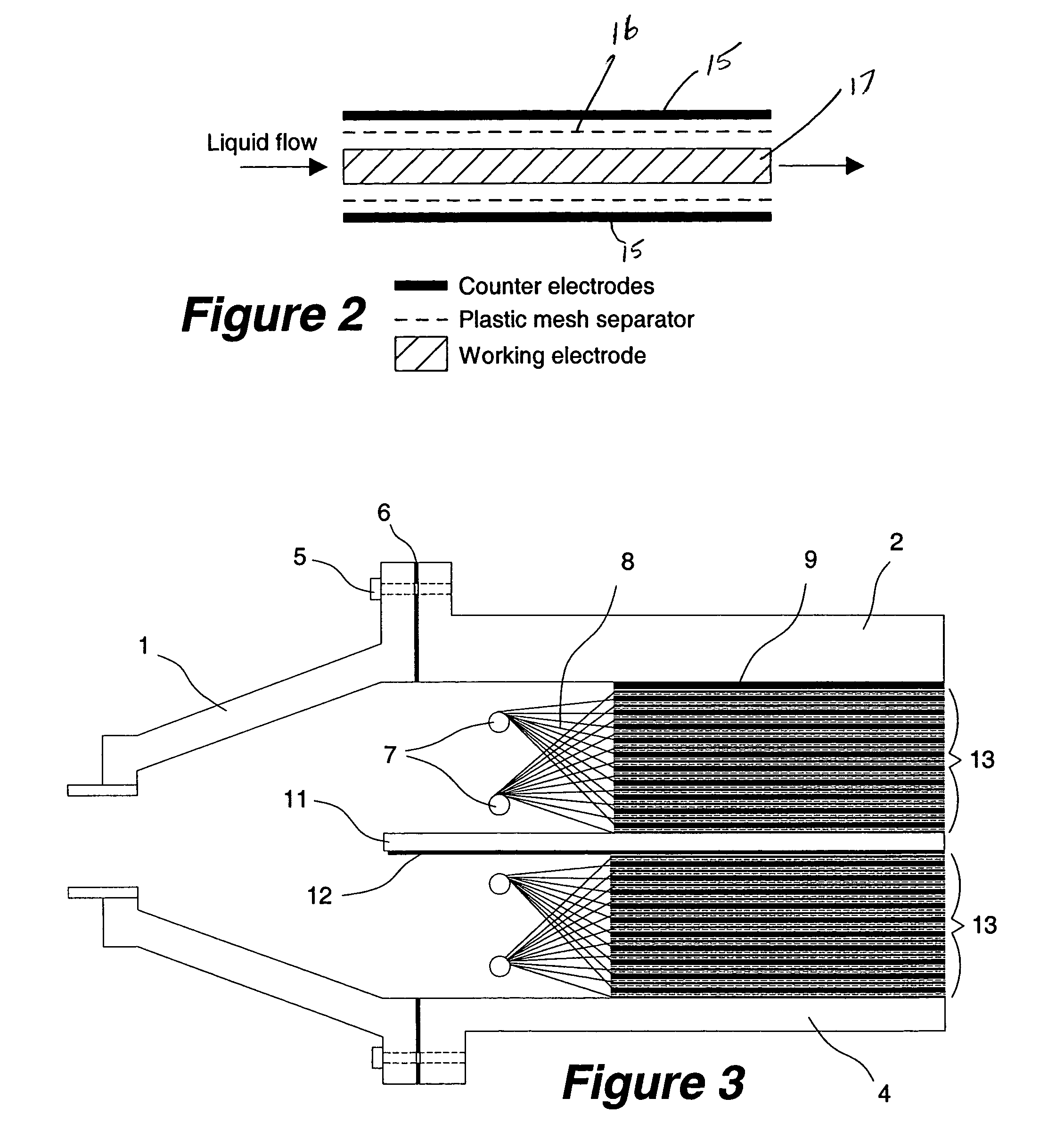
[0040]A superficial channel fluid velocity of 25 cm / s was achieved with less than 5 psi pressure drop (hence a larger scale 1 m electrode length cell would have an acceptable inlet pressure drop of about 15 psi under these conditions). The superficial channel fluid velocity is, in this case, the entrance velocity to each of the channels formed by a working electrode and its pair of polymer mesh separators (as solid counter electrodes were used for this example). The pressure drops measured for various superficial velocities of water are shown in FIG. 8.

[0041]The system mass transfer performance was measured using a ferri / ferrocyanide test solution. The ferri / ferrocyanide solution was made up with 6.1 mM ferricyanide, 1.0 mM ferrocyanide, and 0.2 M sodium sulphate giving a density of 1.02 g / ml. The cell voltage was increased until a current plateau was found. The cell was then held at a potential on the plateau and the flowrate was varied while the cur...

example 2

Test Run Showing Contaminant Removal

[0042]A 10 L test solution of wastewater was treated using the test cell. The solution was recirculated at a flow rate of 7 USGPM (26.6 L / min) and with an applied current of 26 A. The concentrations of the key contaminants in the test solution (a selection of phenol compounds) were followed by sampling and analysis using solid phase microextraction then gas chromatography mass spectroscopy (SPME-GCMS). “Polyacrylate Film Fiber for Solid Phase Microextration of Polar Semivolatiles from Water”, Application note 17, Supelco, Bellefonte, Pa., (1998) describes SPME-GCMS. The cell ran with an average pressure drop of 4.6 psi, and stack module voltages of 3.08 V and 3.09 V giving a cell voltage of 6.17 V (the solution resistance being 57 ohmcm). Over the course of the run the cell temperature increased from 23° C. to 41° C. As can be seen in FIG. 10 the phenols were rapidly removed with the total concentration of the phenols being reduced from about 2600...

example 3

Test Run Showing Cell Self-Heating

[0043]The cell was run in the same manner as described in Example 2, but with a different wastewater solution (31000 ppb total concentration of phenols, 4500 ppm COD, and a solution resistance of 116 ohmcm). In this case the system was insulated to retain the heat generated by the electrochemical cell and the pump. While this test solution started at around 15° C., by the end of the run the solution had reached 64° C., without the use of any supplemental heating. In fact, over the course of the experiment as the solution temperature increased, the cell voltage decreased from around 7.0 V to 6.2 V, resulting in a power savings. After running 13.75 h the total concentration of the phenols was reduced to about 60 ppb, and the COD to about 4200 ppm.


PUM

PropertyMeasurementUnit
voltageaaaaaaaaaa
voltageaaaaaaaaaa
thickaaaaaaaaaa

Abstract

An electrochemical cell design is disclosed for the particular application of the electrochemical treatment of contaminants in water. The cell is designed to allow the treatment of low concentrations of contaminants in low conductivity water efficiently, and to be simple to fabricate. The design incorporates tapered inlet and outlet fluid flow manifolds so that the cell pressure drop will be almost entirely due to fluid contacting the electrodes, thus maximising the effective use of the system pump power. A short anode to cathode distance and thin working electrodes are used to minimise resistive electrical power losses. The parallel slacked arrangement of the electrodes and the smooth inlet and outlet designs leads to relatively even distributions of current density and mass transfer resulting in maximal utilisation of the entire active electrode surface area. The electrodes are connected internally in parallel in monopolar stack modules, and the modules are then connected externally in series, with insulating baffles to minimise current by-pass problems. This provides a simple cell construction (a minimum number of simple insulating baffles) while still simplifying the cell wiring and reducing the cell current demand (allowing lighter wiring to be used).

Description

CROSS-REFERENCE TO RELATED APPLICATION[0001]This application claims priority from U.S. Provisional Application No. 60 / 407,710, filed Sep. 4, 2002.TECHNICAL FIELD[0002]The invention relates to the design of electrochemical cells for the application of the electrochemical treatment of contaminants in water. Further this design incorporates novel ideas to allow the treatment of low concentrations of contaminants in low conductivity water using an efficient and simple (and therefore low fabrication cost) electrochemical cell.BACKGROUND OF THE INVENTION[0003]For water treatment systems running in acidic or poorly buffered neutral solutions, anodes which are stable in acid are required. Such stable anodes are typically fabricated as active coatings on a corrosion resistant valve metal substrate (for example, but not limited to: titanium, tantalum, and zirconium. See, for example, G. P. Vercesi, J. Rolewicz, Ch. Comninellis, E. Plattner, and J. Hinden, “Characterization of DSA-Type Oxygen ...

Claims


Application Information

Patent Timeline
Patent Type & Authority Patents(United States)
IPC IPC(8): C25B9/20C25C7/04C02F1/461C25B9/17C02F1/46C02F1/467
CPCC02F1/46109C02F2101/18C02F2101/345C02F2103/04C02F1/4672C02F2001/46142C02F2001/46152
Inventor GATTRELL, MICHAELGUENA, THIERRYMACDOUGALL, BARRY
Owner NAT RES COUNCIL OF CANADA
Why Eureka
Try Eureka