
Pattern forming method, image forming method, fine particle adsorption pattern forming method, conductive pattern forming method, pattern forming material and planographic printing plate

a technology of conductive pattern and pattern forming, which is applied in the field of pattern forming method, image forming method, fine particle adsorption pattern forming method, etc., can solve the problems of difficult application of method to large area image formation and the like, unsatisfactory quality and resolution of formed image, and work is troublesome, so as to improve the adhesion property of fine particles and improve the adhesion property of conductive materials. , the effect of superior conductivity

Inactive Publication Date: 2007-12-11
FUJIFILM HLDG CORP +1
View PDF47 Cites 26 Cited by
  • Summary
  • Abstract
  • Description
  • Claims
  • Application Information

AI Technical Summary

Benefits of technology

[0346]The polymer compound of the invention having a polarity conversion group may be a homopolymer of one monomer having the above-mentioned functional groups, and a copolymer of 2 or more monomers. It may be a copolymer with another monomer so far as it does not damage the effect of the invention.
[0347]Specific examples of the monomer having the above-mentioned functional groups are shown below.(Specific Examples of Monomer Having Functional Groups Represented by Above-Mentioned General Formulae (I) to (II))
[0348](Specific Examples of Monomer Having Functional Groups Represented by Above-mentioned General Formula (III))
[0350]When the formation of the hydrophilic zone and hydrophobic zone (hydrophilic / hydrophobic patterns) by the step is carried out by heat, it is preferable that the photothermal conversion substance is let be contained in any of the photothermal conversion substance layer separately provided between the graft polymer layer, the polymerization initiation layer and the support or between the polymerization initiation layer and the support substrate, and exposed imagewise by IR laser and the like.
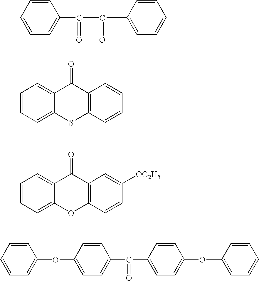
[0351]As the applicable photothermal conversion substance, all of substances can be used so far as they are substances which absorb light such as ultraviolet rays, visible rays, infrared rays and white beam and convert light to heat. Examples of the substance include carbon black, carbon graphite, a pigment, a phthalocyanine-base pigment, iron powder, graphite powder, ferric oxide powder, lead oxide, silver oxide, chromium oxide, iron sulfide and chromium sulfide. In particular, a dye, a pigment or a metal which effectively absorbs infrared rays of a wavelength of 760 nm to 1200 nm is preferable.(Acid Generating Substance)
[0352]When the formation of the hydrophilic zone and hydrophobic zone (hydrophilic / hydrophobic patterns) by the step is carried out by acid hydrolysis, it is preferable that the acid generating substance is let be contained in any of the photothermal conversion substance layers which were separately provided between the graft polymer layer, the polymerization initiation layer and the support, or between the polymerization initiation layer and the support substrate, and exposed imagewise by active beam.

Problems solved by technology

However, although fine and precise patterns can be formed according to the technique, a specific material must be used, and it has been difficult to apply the method to large area image formation and the like.
However, the method of forming the hydrophilic / hydrophobic pattern requires an expensive high power laser because high energy is required for removing the hydrophilic layer, and further, the quality and the resolution of the formed image are also unsatisfactory.
However, there are problems in that this method requires 4 steps for forming the hydrophilic / hydrophobic pattern and the work is troublesome.
According to the method, a layer of fine particles can be evenly aggregated and uniformly arranged, but it is difficult to obtain a patterned arrangement in a desired zone.
According to the method, it is possible to prepare a pattern of fine particles, but since the fine particles are merely physically adhered and not fixed, they are easily released, and the pattern is not suitable for uses as various devices.
However, since the procedure of the method is difficult and the solvent evaporation rate must be controlled for preparing ordered particle laminates, the particle laminates cannot be easily prepared.
Further, since an area capable of being prepared is small, this method is not suitable for preparing a laminate with a large area.
Furthermore, adsorption strength between a substrate and fine particles laminated in a pattern shape is weak.
Therefore a complicated process has to be carried out.
However, the method has problems in preparing conductive fine patterns in that fine patterns having an order of several microns cannot be prepared because of the drawing by ink jet, and in that, while patterns having an order of several tens of microns can be prepared, conductivity is unstable because of low viscosity of the metal paste and difficulty in lamination, etc.
Further, since the conductive layer which is drawn is only set on the substrate, there have also been problems with respect to adhesion property between the substrate and the conductive layer.

Method used


Image

  • Pattern forming method, image forming method, fine particle adsorption pattern forming method, conductive pattern forming method, pattern forming material and planographic printing plate
  • Pattern forming method, image forming method, fine particle adsorption pattern forming method, conductive pattern forming method, pattern forming material and planographic printing plate
  • Pattern forming method, image forming method, fine particle adsorption pattern forming method, conductive pattern forming method, pattern forming material and planographic printing plate

Examples


synthesis example 1

(Synthesis of Specific Polymerization Initiation Polymer A)

[0416]To a 300 ml three necked flask, 30 g of propylene glycol monomethyl ether (MFG) was added to be heated at 75° C. Thereto, a solution of 8.1 g of [2-(acryloyloxy)ethyl](4-benzoylbenzyl)dimethylammonium bromide, 9.9 g of 2-hydroxyethyl methacrylate, 13.5 g of isopropyl methacrylate, 0.43 g of dimethyl-2,2′-azobis(2-methyl propionate) and 30 g of MFG was added dropwise over 2.5 hours. Then, the reaction temperature was raised to 80° C., and further reaction was made for 2 hours to obtain the specific polymerization initiation polymer A described below. The numerical values shown in the following structures show the molar copolymerization ratio of respective repeating units.

[0417]

synthesis example 2

(Synthesis of Specific Polymerization Initiation Polymer B)

[0418]To a 300 ml three necked flask, 30 g of propylene glycol monomethyl ether (MFG) was added to be heated at 75° C. Thereto, a solution of 5.1 g of 4-methacryloyloxy-benzophenone, 9.9 g of 2-hydroxyethyl methacrylate, 9.8 g of isopropyl methacrylate, 3.97 g of [2-(methacryloyloxy)ethyl]trimethylammonium bromide, 0.43 g of dimethyl-2,2′-azobis(2-methyl propionate) and 30 g of propylene glycol monomethyl ether (MFG) was added dropwise over 2.5 hours. Then, the reaction temperature was raised to 80° C., and further reaction was made for 2 hours to obtain the specific polymerization initiation polymer B described below. The numerical values shown in the following structures show the molar copolymerization ratio of respective repeating units.

[0419]

synthesis example 3

(Synthesis of Specific Polymerization Initiation Polymer C)

[0420]To a 300 ml three necked flask, 30 g of propylene glycol monomethyl ether (MFG) was added to be heated at 75° C. Thereto, a solution of 8.1 g of [2-(acryloyloxy)ethyl](4-benzoylbenzyl)dimethylammonium bromide, 9.9 g of 2-aminoethyl methacrylate, 13.5 g of isopropyl methacrylate, 0.43 g of dimethyl-2,2′-azobis(2-methyl propionate) and 30 g of propylene glycol monomethyl ether (MFG) was added dropwise over 2.5 hours. Then, the reaction temperature was raised to 80° C., and further reaction was made for 2 hours to obtain the specific polymerization initiation polymer C described below. The numerical values shown in the following structures show the molar copolymerization ratio of respective repeating units.

[0421]

1. Examples related to pattern forming method, image forming method, pattern forming material, and planographic printing plate


PUM

PropertyMeasurementUnit
temperatureaaaaaaaaaa
wavelengthaaaaaaaaaa
temperatureaaaaaaaaaa

Abstract

The invention provides a pattern forming method including providing a polymerization initiation layer which is obtained by fixing, by a cross-linking reaction, a polymer having functional groups having polymerization initiation ability and cross-linking groups at side chains, on a support, and forming a pattern including a preparation zone and a non-preparation zone of a graft polymer by preparing the graft polymer on the surface of the polymerization initiation layer using graft polymerization, by contacting a compound having a polymerizable group on the polymerization initiation layer and supplying energy imagewise; an image forming method which applies the pattern forming method; a pattern forming material; and a planographic printing plate. A fine particle adsorption pattern forming method and a conductive pattern forming method are also provided.

Description

CROSS-REFERENCE TO RELATED APPLICATION[0001]This application claims priority under 35 USC 119 from Japanese Patent Application Nos. 2003-115984, 2003-129150, 2003-179442 and 2004-79009, the disclosure of which is incorporated by reference herein.BACKGROUND OF THE INVENTION[0002]1. Field of the Invention[0003]The present invention relates to a pattern forming method, to an image forming method, a fine particle adsorption pattern forming method, and a conductive pattern forming method, in which substances having various functionalities are adhered in a pattern shape as applications of the pattern forming method, and to a pattern forming material and a planographic printing plate prepared by the pattern forming method.[0004]2. Description of the Related Art[0005]Techniques for forming a fine pattern have recently attracted attention in various fields. In particular, methods for forming fine hydrophilic / hydrophobic patterns have attracted attention. For example, as a method of forming h...

Claims


Application Information

Patent Timeline
Patent Type & Authority Patents(United States)
IPC IPC(8): G03F7/26G03F7/028G03F7/095G03F7/14B41C1/10G03F7/00G03F7/004G03F7/027G03F7/029G03F7/031G03F7/033G03F7/038G03F7/039G03F7/16G03F7/28G03F7/40H05K3/10
CPCG03F7/0012G03F7/40G03F7/031G03F7/033G03F7/0388G03F7/0392G03F7/095G03F7/0955G03F7/168G03F7/28G03F7/0045G03F7/027G03F7/029G03F7/0295G03F7/038
Inventor KANO, TAKEYOSHIKAWAMURA, KOICHI
Owner FUJIFILM HLDG CORP
Learn More