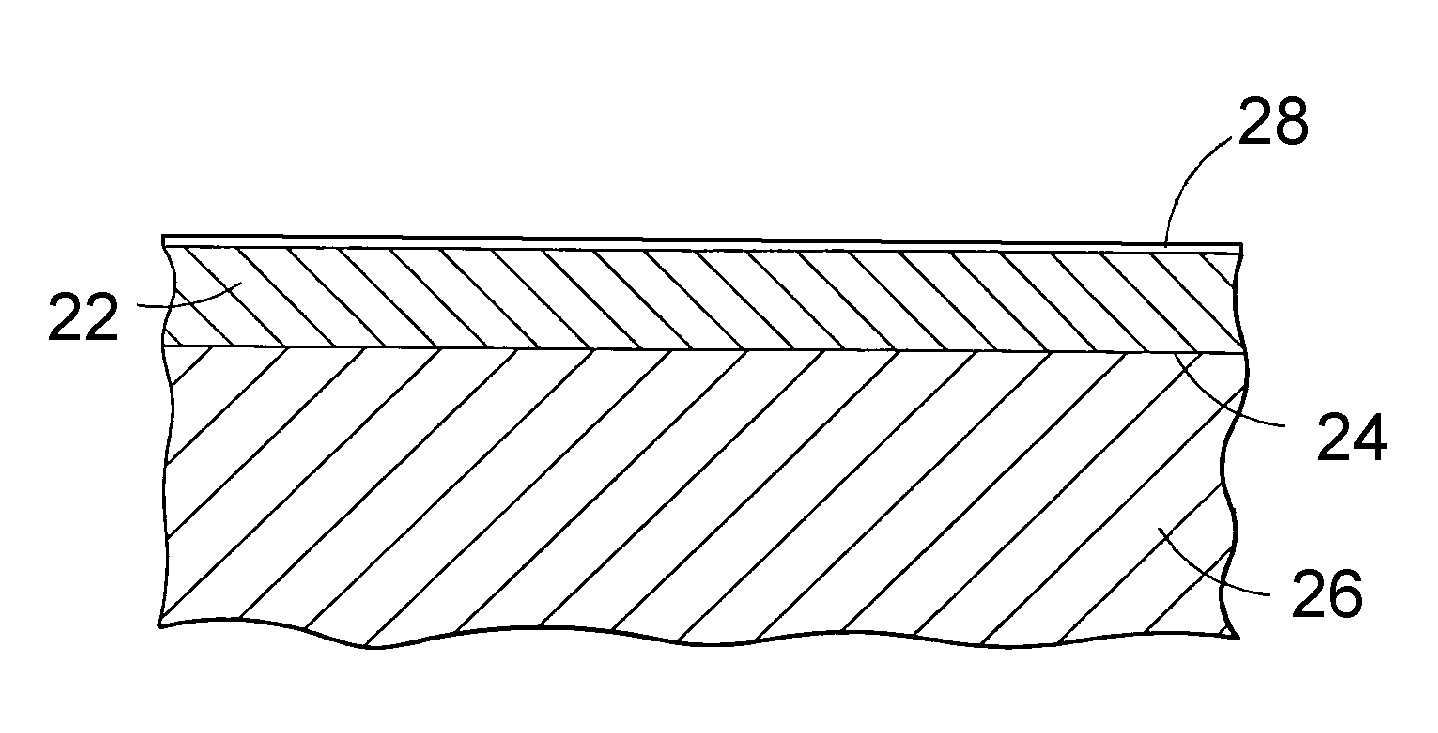
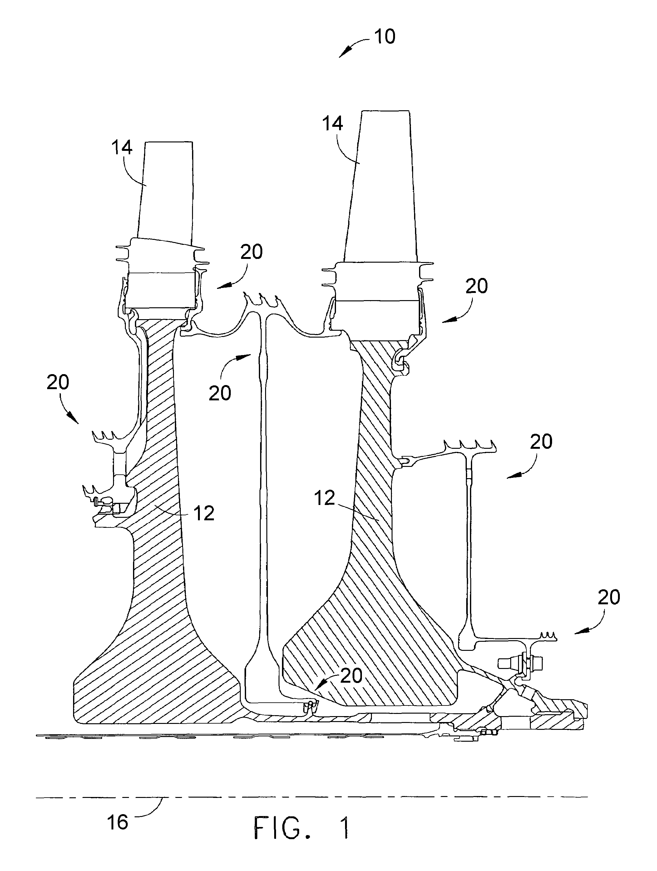
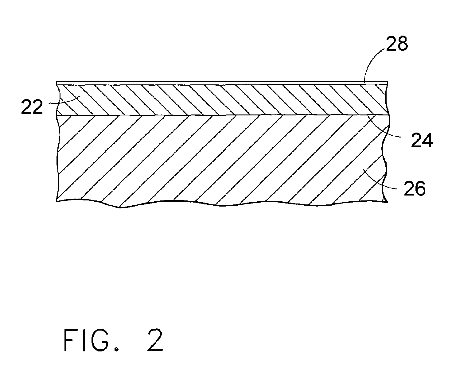
[0007]The present invention provides an environmental coating suitable for use on turbine components, such as turbine disks and turbine seal elements, and particularly those formed of alloys susceptible to oxidation and hot corrosion. The environmental coating has a metallic composition that is adherent, resistant to oxidation and hot corrosion, and both physically and chemically compatible with disk and seal alloys, and therefore capable of providing reliable long-term protection from oxidation and hot corrosion.
[0008]The metallic composition of the environmental coating is predominantly a
solid solution phase of
nickel, iron, and / or
cobalt, preferably gamma-Ni matrix, gamma-Co matrix, or a mixture of
nickel and
cobalt. The composition further contains about 18 weight percent to about 60 weight percent
chromium. The
lower limit of this range ensures that the environmental coating will form a protective
chromia (Cr2O3) scale while also exhibiting high
ductility, good corrosion resistance, and metallurgically bonding to a turbine disk
alloy for adhesion. Based on the Ni—Cr
phase diagram, the upper limit of the
chromium range is to avoid the formation of single-phase alpha chromium. The environmental coating may be as thick as about 250 micrometers, though thicknesses of less than 125 micrometers and more preferably not more than fifty micrometers are preferred to provide a sufficiently thin and ductile coating that enables compressive stresses to be induced in the underlying substrate through
shot peening without
cracking the environmental coating.
[0009]The composition set forth above provides for a very ductile environmental coating with excellent corrosion and
oxidation resistance, though with limited strength. A coating with these properties is suitable for protecting a turbine disk or seal, as the coating is not required to support a substantial load during operation, and fatigue performance is essentially determined by the underlying substrate. In particular, the environmental coating does not adversely
impact the fatigue properties of the turbine disk or seal, in that its very high
ductility resists
crack initiation and its excellent
environmental resistance drives
crack initiation sites internally within the substrates, where grain facets, inclusions, and other common defects are likely to initiate
cracking.
[0010]The environmental coating as described above can be modified to achieve certain properties. For example, the coating may contain additions of aluminum to enhance corrosion and
oxidation resistance. Suitable
aluminum levels in the environmental coating are generally in the range of about 4 to about 8 weight percent, in inverse proportion to the chromium content of the coating. For example, a chromium content of about 18 weight percent allows for an aluminum content of up to about 8 weight percent, a chromium content of about 35 weight percent allows for an aluminum content of up to about 6 weight percent, and a chromium content of about 60 weight percent allows for an aluminum content of up to about 4 weight percent. Notably, the aluminum content is intentionally less than that required for the onset of beta-phase
NiAl formation (about 13 weight percent aluminum), which is avoided due to the low ductility of beta-phase
NiAl that can negatively affect the
low cycle fatigue life of a turbine disk. However, up to about 10
volume percent of the beta-
NiAl phase is believed to be tolerable, as such a level is not continuous and therefore would not be prone to crack propagation. The aluminum content of the environmental coating is also less than the nominal aluminum content for the gamma prime
nickel aluminide phase (Ni3Al), and as a result the coating may contain limited amounts of the gamma prime phase.
[0012]As noted above, desired properties of the composition are high ductility and excellent corrosion and oxidation resistance, with strength being of secondary concern since load-bearing and fatigue performance are to be determined by the underlying substrate. Nonetheless, the environmental coating may be optionally strengthened with
tungsten,
molybdenum,
tantalum,
rhenium,
titanium,
niobium,
vanadium, and / or a
platinum group
metal (PGM) to improve
fatigue resistance. However, additions of these elements are preferably limited to less than 25 weight percent combined, as they can negatively affect corrosion and oxidation resistance, especially
tungsten and
molybdenum. With such limited additions, strengtheners can enable the environmental coating to bear some of the load during operation of a turbine disk, though maintaining sufficient ductility and
environmental resistance to avoid surface-initiated
fatigue cracking.
[0013]In view of the above, it can be seen that a significant
advantage of this invention is that the environmental coating provides protection from oxidation and corrosion in a form suitable for use on turbine components, and particularly on turbine disks and seals formed of polycrystalline superalloys. The environmental coating has a composition whose CTE closely matches that of superalloys widely used for turbine disks and sealing elements, and exhibits limited
mechanical property interaction with such superalloys over
extended time at temperature. Furthermore, the material of the environmental coating is capable of being metallurgically bonded to such superalloys to be highly resistant to spalling. Finally, the environmental coating is compatible with
processing typically associated with polycrystalline superalloys used to form turbine disks and sealing elements. In particular, the ductility and limited thickness of the environmental coating permits the surface of the component to be peened to induce a
residual compressive stress in the turbine disk or seal, without cracking the environmental coating.

