

Self-ionized and capacitively-coupled plasma for sputtering and resputtering
a capacitive-coupled plasma and self-ionized technology, applied in the direction of vacuum evaporation coating, electrolysis components, coatings, etc., can solve the problems of introducing reliability problems, disadvantageous wide distribution, and difficult reflow ou
- Summary
- Abstract
- Description
- Claims
- Application Information
AI Technical Summary
Benefits of technology
Problems solved by technology
Method used
Image

Examples
Embodiment Construction
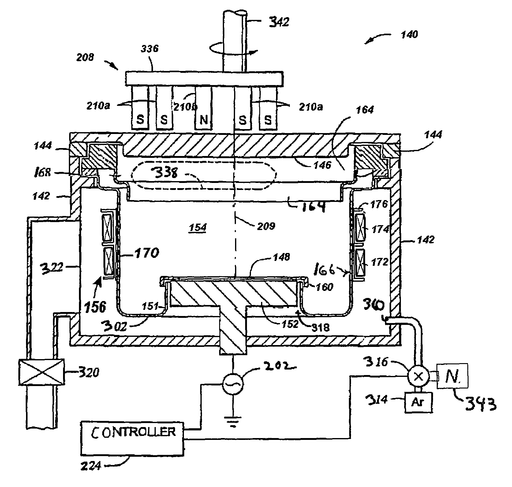
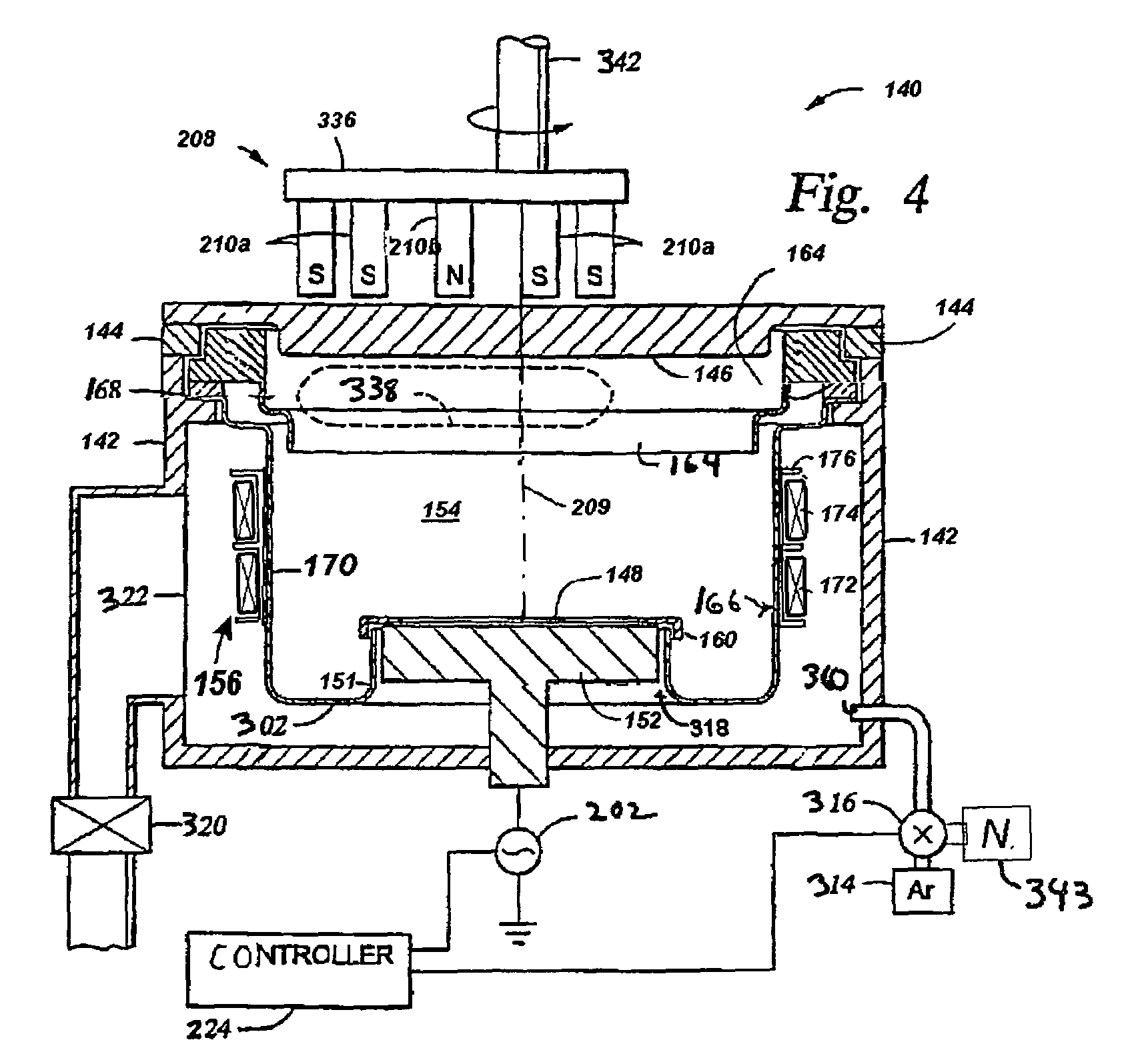
[0024]One embodiment of the present inventions is directed to sputter depositing a liner material such as tantalum or tantalum nitride, by combining long-throw sputtering, self-ionized plasma (SIP) sputtering and capacitively-coupled plasma (CCP) resputtering in one chamber. In a preferred embodiment, a magnetic field generated by an electromagnetic coil confines the plasma generated by capacitive coupling to increase the plasma density and hence the ionization rate. Long-throw sputtering is characterized by a relatively high ratio of the target-to-substrate distance to the substrate diameter. Long-throw SIP sputtering promotes deep hole coating of both the ionized and neutral deposition material components. CCP resputtering can reduce the thickness of layer bottom coverage of deep holes to reduce contact resistance.
[0025]SIP tends to be promoted by low pressures of less than 5 milliTorr. SIP, particularly at these low pressures, tends to be promoted by magnetrons having relatively ...
PUM
| Property | Measurement | Unit |
|---|---|---|
| power | aaaaa | aaaaa |
| power | aaaaa | aaaaa |
| voltage | aaaaa | aaaaa |
Abstract
Description
Claims
Application Information