
Organic electroluminescent device

a technology of electroluminescent devices and organic elements, which is applied in the direction of discharge tube luminescnet screens, natural mineral layered products, etc., can solve the problems of inability to achieve high luminous efficiency, inconvenient practical use of elements utilizing phosphorescent molecules of ir(ppy)3, although highly efficient, etc., to achieve high driving stability, improve the driving stability and heat resistance of organic el elements, and improve the effect of heat resistan

Inactive Publication Date: 2009-09-01
NIPPON STEEL CHEMICAL CO LTD
View PDF9 Cites 1 Cited by
  • Summary
  • Abstract
  • Description
  • Claims
  • Application Information

AI Technical Summary

Benefits of technology

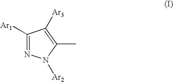
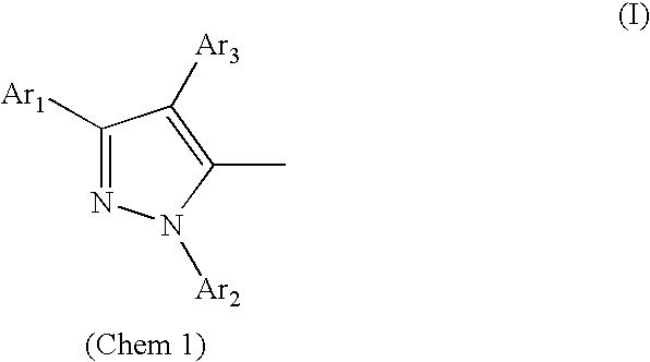
The patent text describes an improvement in the driving stability and heat resistance of organic electroluminescent elements. The invention provides an organic electroluminescent element that performs with high efficiency and high driving stability. The invention relates to an organic electroluminescent element comprising an anode, organic layers, and a cathode, with at least one of the organic layers containing a light-emitting layer containing a host material and a dopant material. The host material is a pyrazole-derived compound that forms a thin film of stable shape, has a high glass transition temperature, and efficiently transfers holes and electrons. The pyrazole-derived compound has a pyrazole structure represented by formula I, with Ar1-Ar3 being hydrogen or substituted or unsubstituted aromatic hydrocarbon groups. The compound has a high glass transition temperature, is stable, and has low impurity levels. The invention also provides a hole-blocking layer between the light-emitting layer and the cathode or an electron-transporting layer between the light-emitting layer and the cathode. The pyrazole-derived compound used in the light-emitting layer has a pyrazole structure represented by formula I, with Ar1-Ar3 being hydrogen or substituted or unsubstituted aromatic hydrocarbon groups. The compound has a high glass transition temperature, is stable, and has low impurity levels. The invention also provides an method for manufacturing the organic electroluminescent element using a pyrazole-derived compound as the host material.

Problems solved by technology

Thereafter, the use of europium complexes was attempted, but it was unable to obtain high luminous efficiency.
The organic EL elements utilizing phosphorescent molecules of Ir(ppy)3 described in non-patent literature 2, although highly efficient, are not suitable for practical use because of their insufficient driving stability at the present time (Jpn. J. Appl. Phys., Vol. 38, L1502, 1999).
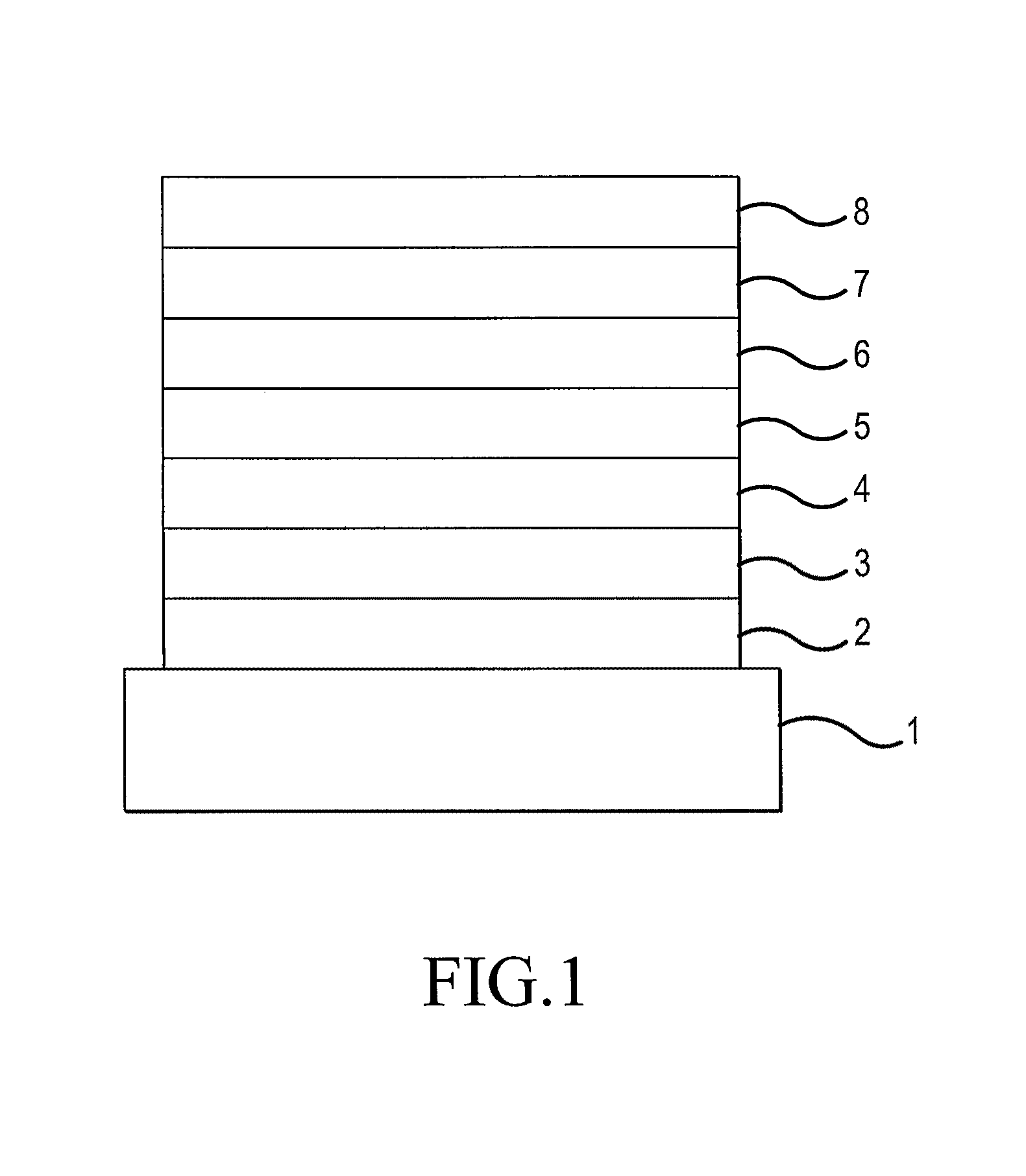
The main cause of the deterioration of the aforementioned driving stability is presumed to be the deterioration of the shape of thin film of the light-emitting layer in the structure of an element such as substrate / anode / hole-transporting layer / light-emitting layer / hole-blocking layer / electron-transporting layer / cathode or substrate / anode / hole-transporting layer / light-emitting layer / electron-transporting layer / anode.
It is likely that the deterioration of the shape of thin film is attributable to crystallization (or cohesion) of thin organic amorphous films caused by generation of heat during driving of the element and poor heat resistance is due to low glass transition temperature (Tg) of the material in use.
Because of their high symmetry and low molecular weight, these compounds readily undergo crystallization or cohesion and suffer deterioration of the shape of thin film.
Besides, their crystallizability is too high to allow observation of their Tg.
Such instability of the shape of thin film of the light-emitting layer adversely affects the performance of an element, for example, by shortening the driving life and lowering the heat resistance.
For the reasons described above, a difficult problem facing phosphorescent organic electroluminescent elements at the present time is their driving stability.
However, they face the aforementioned problem.

Method used


Image

  • Organic electroluminescent device
  • Organic electroluminescent device
  • Organic electroluminescent device

Examples


synthetic example 1

[0076]In a 300-ml four-necked flask were placed 10.9 g (0.27 mole) of sodium hydroxide, 52.7 g of ethanol and 98.3 g of deionized water. The mixture was stirred at room temperature for 10 minutes until the sodium hydroxide dissolved and 26.1 g (0.22 mole) of acetophenone was added. Thereafter, the mixture was cooled by ice water and 14.1 g (0.11 mole) of terephthaldehyde was added. After the addition, the mixture was heated under reflux with stirring for 4 hours. Upon completion of the reaction, the reaction mixture was cooled to room temperature and a solid was collected by filtration. The solid was made into a slurry by ethanol and dried under reduced pressure to give 28.5 g of a yellow powder. This powder was analyzed by thin-layer chromatography (TLCG) to be a single product. Analysis of this product by mass spectrometry showed that its molecular weight was 338 and identical with that of the target compound calcone. The yield of the isolated product was 80.1%.

synthetic example 2

[0077]In a 2000-ml four-necked flask were placed 20.1 g (0.36 mole) of potassium hydroxide and 1482.7 g of ethanol. The mixture was stirred at room temperature until the potassium hydroxide dissolved and 32.8 g (0.10 mole) of the calcone obtained in Synthetic Example 1 was added at room temperature. Further, 40.4 g (0.37 mole) of phenylhydrazine was added at room temperature. After the addition, the mixture was heated under reflux with stirring for 2.5 hours. Upon completion of the reaction, the reaction mixture was cooled to room temperature and a solid was collected by filtration. The solid was washed with methanol and hexane and dried under reduced pressure to give 42.1 g of a yellow powder. This powder was confirmed to be a single product by TLCG. Analysis of this product by mass spectrometry showed that its molecular weight was 518 and identical with that of the target pyrazoline compound. The yield was 83.7%.

synthetic example 3

[0078]In a 500-ml four-necked flask was placed 354.4 g (4.480 moles) of pyridine. Then, 57.6 g (0.19 mole) of antimony pentachloride was added slowly in drops so that no vigorous generation of heat occurred. After the dropwise addition, the mixture was allowed to cool to room temperature and 25.9 g (0.050 mole) of the pyrazoline compound obtained in Synthetic Example 2 was added. After this addition, the mixture was stirred at room temperature for 3.5 hours. Upon completion of the reaction, a solid was recovered by filtration. The solid was washed with ethanol to give 42.1 g of a pale brown powder. The powder was recrystallized twice from methylene chloride to give 18.3 g of white crystals. Analysis of the crystals by TLCG confirmed the formation of a single product and analysis of the product by mass spectrometry showed that its molecular weight was 514 and identical with that of the target compound 5,5′-(1,4-phenylene)bis[1,3-diphenyl-1H-pyrazole] (hereinafter referred to as PBP)....


PUM

PropertyMeasurementUnit
wt %aaaaaaaaaa
transmittanceaaaaaaaaaa

Abstract

This invention provides an organic electroluminescent element (organic EL element) utilizing phosphorescence which emits light efficiently with high luminance at low current density, shows good driving stability and is applicable to display devices such as flat panel displays and illuminating devices. The element comprises an anode, organic layers and a cathode piled one upon another on a substrate, at least one of the organic layers is a light-emitting layer containing a host material and a dopant material and a pyrazole-derived compound having 2-4 pyrazole structures represented by the following formula I in the same molecule is used as said host material;wherein, Ar1-Ar3 are independently hydrogen or substituted or unsubstituted aromatic hydrocarbon groups and at least one of Ar1-Ar3 is a group other than hydrogen.

Description

FIELD OF TECHNOLOGY[0001]This invention relates to an organic electroluminescent element and, more particularly, to a thin-film device which emits light when an electrical field is applied to its organic light-emitting layer.BACKGROUND TECHNOLOGY[0002]In the development of electroluminescent elements utilizing organic materials (hereinafter referred to as organic EL element), the kind of electrodes was optimized for the purpose of improving the electron-injecting efficiency from the electrode and an element in which a hole-transporting layer of an aromatic diamine and a light-emitting layer of 8-hydroxyquinoline aluminum complex are disposed as thin films between the electrodes has been developed (Appl. Phys. Lett., Vol. 51, p. 913, 1987) to bring about a noticeable improvement in luminous efficiency over the conventional elements utilizing single crystals of anthracene and the like. Following this, the developmental works of organic EL elements have been focused on their commercial...

Claims


Application Information

Patent Timeline
Patent Type & Authority Patents(United States)
IPC IPC(8): H01L51/54C07D231/12C09K11/06H05B33/14H10K99/00
CPCC09K11/06H01L51/0067H01L51/5016H05B33/14C09K2211/1007C09K2211/1011C09K2211/1029C09K2211/1037C09K2211/1044C09K2211/185H01L51/0052C09K2211/1092Y10S428/917H10K85/615H10K85/654H10K50/11H10K2101/10
Inventor YOSHITAKE, OSAMUMIYAZAKI, HIROSHISUZAKI, DAISUKEYAMADA, YU
Owner NIPPON STEEL CHEMICAL CO LTD
Learn More