Charged particle beam apparatus

a particle beam and apparatus technology, applied in the direction of vacuum obtaining/maintenance, positive displacement liquid engine, therapy, etc., can solve the problems of electric discharge, rare gases and fluorocarbons are hardly removed, and electrochemically stable gases such as rare gases and fluorocarbons are difficult to remove. achieve the effect of high vacuum

Inactive Publication Date: 2009-11-10
HITACHI HIGH-TECH CORP
View PDF10 Cites 21 Cited by
  • Summary
  • Abstract
  • Description
  • Claims
  • Application Information

AI Technical Summary

Benefits of technology

[0010]An object of the present invention is to provide a compact charged particle beam apparatus with a non-evaporable getter pump in which high vacuum is maintained even during electron beam emission without generating foreign particles.
[0012]Preferably the vacuum pump should be a sputter ion pump with a high efficiency in rare gas removal or a noble ion pump. A remarkable effect of the use of such a pump is a substantial increase in the time for which high vacuum is maintained. A turbo-molecular pump may be used instead of an ion pump.
[0013]In placing a non-evaporable getter pump in the apparatus, the first point to note is that means to support the sheet getter pump should be designed to avoid contact of non-evaporable getter alloy with other parts (or hold it in a way not to contact anything). The second point is that if a pellet made by sintering fine particles of non-evaporable getter alloy is used, a small chamber should be provided on a column side wall and used as an auxiliary pump. Instead of fine particles of non-evaporable getter alloy, relatively large particles of about 3 mm square (bulk alloy) may be used. The use of such bulk alloy particles considerably reduces the possibility of generation of foreign particles upon contact. However, in this case, since surface area of the non-evaporable getter alloy is smaller, the pumping speed is lower. Taking the above advantage and disadvantage into consideration, grained getter alloy is held in a container partitioned by a mesh and placed in the vicinity of a typical built-in heater for a charged particle beam.
[0014]Furthermore, the space between the most downstream electron gun chamber and the sample chamber is sealed except an opening through which an electron beam passes. However, if an adequate level of conductance exists between the chambers, the need for an ion pump or turbo-molecular pump is completely able to eliminate.
[0032]According to the invention, it is possible to realize a compact charged particle beam apparatus with non-evaporable getter pumps which can maintain high degree of vacuum even during emission of an electron beam without generating foreign particles.

Problems solved by technology

This implies a problem that electrochemically stable gases such as rare gases and fluorocarbon are hardly removed because they are completely in equilibrium.
Consequently there is a problem that getter alloy particles exposed on the surface might come off and become foreign particles, clogging an opening in an electron optics or they might be charged, causing an electric discharge.

Method used


Image

  • Charged particle beam apparatus
  • Charged particle beam apparatus
  • Charged particle beam apparatus

Examples


first embodiment

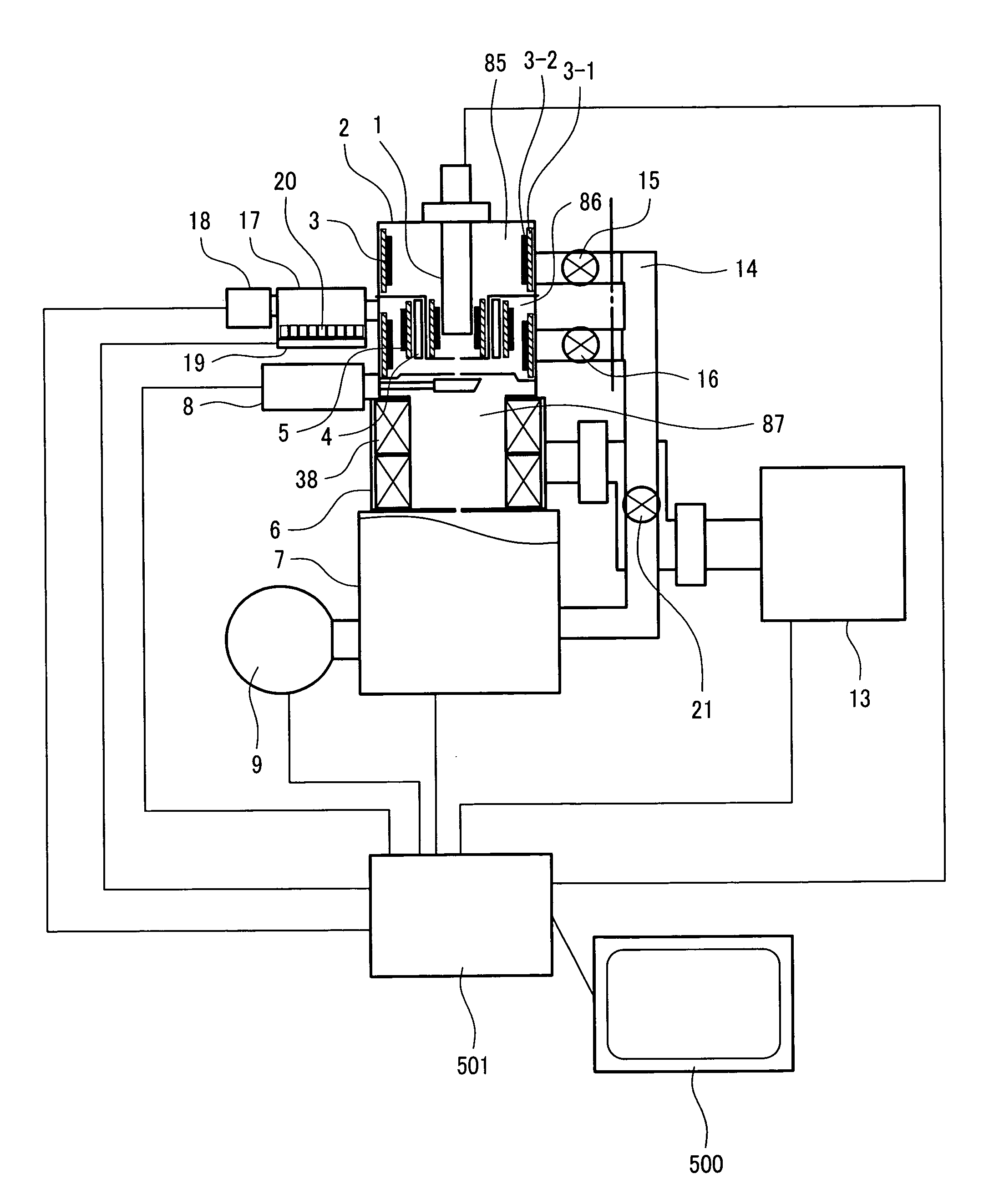
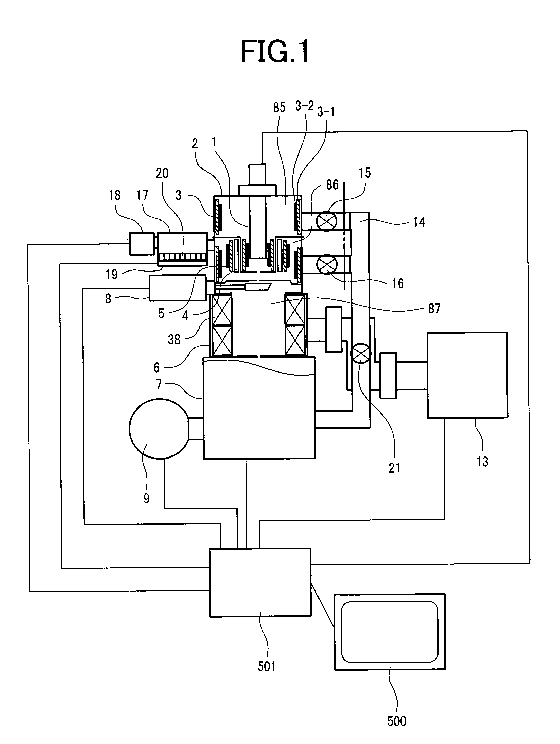
[0050]FIG. 1 shows the structure of a charged particle beam apparatus according to the first embodiment of the invention. This embodiment employs a thermal field emitter electron gun (TFE) as an electron source. This electron source 1 is fitted to a flange with a diameter of 152 mm and connected with a feedthrough to electrodes (suppressor, extractor, tip) (not shown). The electron source 1 is inserted and fixed in an electron gun column 2. The electron gun column 2 consists of a first vacuum chamber 85 and a second vacuum chamber 86 with an opening between them. This leads to a differential pumping effect of a non-evaporable getter pump which increases the achieved degree of vacuum of the first vacuum chamber 85 (decreases the pressure).

[0051]Another possible design for more compactness is that the first vacuum chamber 85 and the second vacuum chamber 86 are integrated into one vacuum chamber to omit part of the pipe including a valve 16 in a rough pumping port 14. The rough pumpin...

second embodiment

[0077]While the first embodiment concerns an apparatus which uses an auxiliary pump, the second embodiment concerns an apparatus in which a column does not requires any type of auxiliary pump such as an ion pump or turbo-molecular pump.

[0078]Referring to FIG. 7, the basic structure of the apparatus is almost the same as the first embodiment except the following points. First, in the second embodiment, the ion pump 13 for the electro-optics column 6 is eliminated and instead a valve 300 is connected with the sample chamber 7.

[0079]Carbon contaminants on parts with low heat resistance which cannot withstand the baking temperature of 200° C. or so are cleaned in advance. It is particularly important to remove all oily residues on machined surfaces of metallic parts. This reduces generation of hydrocarbon gases which a non-evaporable getter pump hardly removes.

[0080]Although generation of hydrocarbon gases is reduced, all such gases are not removed. Therefore, the second difference from...

third embodiment

[0083]This embodiment concerns non-evaporable getter alloy in a form other than a sheet or pellet. Specifically, the getter alloy size should be on the millimeter order (less than 10 mm) and typically, grained non-evaporable getter alloy of approx. 3 mm square is easy to handle. The alloy is a bulk alloy of the above size and generates no foreign particles upon contact. However, since the effective surface area of the bulk alloy is smaller, the pumping speed tends to be lower.

[0084]By contrast, the pellet type is porous because it is made by sintering fine particles of several microns to several hundreds of microns and therefore in case of the pellet type, the surface area is larger but fine particles easily come off upon contact.

[0085]In order to increase the surface area of grained non-evaporable getter alloy, its surface should have a convexo-concave shape. The surface of the grained non-evaporable getter alloy used in this embodiment has a convexo-concave pattern which is repeat...


PUM


Abstract

There is provided a compact charged particle beam apparatus with a non-evaporable getter pump which maintains high vacuum even during emission of an electron beam without generating foreign particles. The apparatus comprises: a charged particle source; a charged particle optics which focuses a charged particle beam emitted from the charged particle source on a sample and performs scanning; and means of vacuum pumping which evacuates the charged particle optics. The means of vacuum pumping has a differential pumping structure with two or more vacuum chambers connected through an opening in series. A pump made of non-evaporable getter alloy is placed in an upstream vacuum chamber with a high degree of vacuum, and a gas absorbing surface of the non-evaporable getter alloy is fixed without contact with another part.

Description

CLAIM OF PRIORITY[0001]The present invention claims priority from Japanese patent applications JP 2006-128962 filed on May 8, 2006, and JP 2005-325559 filed on Nov. 10, 2005, the contents of which are hereby incorporated by reference into this application.BACKGROUND OF THE INVENTION[0002]The present invention relates to charged particle beam apparatuses such as electron microscopes and focused ion beam systems.[0003]A conventional scanning electron microscope (SEM) creates an image as follows: an electron beam emitted from an electron gun consisting of a field emitter or thermal field emitter electron source is accelerated and made a thin electron beam by an electron lens; this beam as a primary electron beam is scanned over a sample through a scanning deflector and generated secondary electrons or backscattered electrons are detected. The material of the electron source for a general-purpose SEM is tungsten. The material of the electron source for semiconductor observation may be t...

Claims


Application Information

Patent Timeline
Patent Type & Authority Patents(United States)
IPC IPC(8): A61N5/00G21G5/00
CPCH01J37/18H01J37/28H01J2237/31749H01J2237/1825H01J2237/188H01J2237/022
Inventor KATAGIRI, SOUICHIOHSHIMA, TAKASHIAGEMURA, TOSHIHIDESATO, MITSUGU
Owner HITACHI HIGH-TECH CORP
Why Eureka
Try Eureka