Membrane separation process using mixed vapor-liquid feed

a membrane separation and vapor liquid technology, applied in the direction of hydrocarbon purification/separation, water/sewage treatment, hydrocarbons, etc., can solve the problems of limiting the permeation rate of aromatic content, difficult and inefficient separation with simple pervaporation membrane systems, and significant drop in temperature and loss of permeate flux, so as to reduce the effect of high vapor pressure of these compounds on the permeation rate and reduce the effect of high vapor pressur

Active Publication Date: 2010-09-28
EXXON RES & ENG CO
View PDF7 Cites 34 Cited by
  • Summary
  • Abstract
  • Description
  • Claims
  • Application Information

AI Technical Summary

Benefits of technology

[0007]In the present invention, the competitive permeation of low boiling aliphatics can be largely avoided allowing effective performance with enhanced aromatics selectivity at only moderate membrane backpressures. The present invention includes feeding the gasoline or naphtha in a mixed vapor / liquid phase state, at a controlled extent of vaporization and then operating the membrane module in an essentially adiabatic mode. This eliminates the need for any predistillation. The heavier aromatic rich portion of the vapor preferentially condenses onto the membrane, enhancing aromatics permeation, and the heat of condensation of this portion of the vapor provides the heat needed to vaporize the permeate on the back side of the membrane. As the aromatics permeate the membrane (depleting aromatic content of the liquid contacting the membrane) they are replenished by the continual preferential condensation of the higher boiling aromatics contained in the vapor portion of the feed.

Problems solved by technology

Adiabatic operation in conventional membrane separation systems can result in a significant drop in temperature and loss of permeate flux.
However, the wide boiling range, variable composition and volatility of market gasolines make separation with simple pervaporation membrane systems difficult and inefficient.
The lower boiling, lower octane aliphatic components in gasoline permeate competitively with the higher boiling higher-octane aromatics, thereby limiting the permeation of the aromatic content.
The competitive permeation of aliphatic compounds also limits membrane selectivity, thereby reducing aromatic selectivity.
High yields of aromatic permeate require considerable energy, which reduces the overall efficiency of the membrane system.
Complex systems using pre-fractionation, multi-stage membrane processing, and / or recycle with post-fractionation, to address these issues are generally not desirable for efficient membrane systems.

Method used


Image

  • Membrane separation process using mixed vapor-liquid feed
  • Membrane separation process using mixed vapor-liquid feed
  • Membrane separation process using mixed vapor-liquid feed

Examples


example 1

Pervaporation Membrane

[0023]An aromatic selective membrane of the type described in U.S. Pat. No. 5,670,052 was used to concentrate aromatics from the gasoline in the permeate. The polyimide-polyadipate membrane used was crosslinked with diepoxidecyclooctane (DECO). The polyimide hard segment contains pyromellitic dianhydride (PMDA) and 4,4′-methylene bis(2-chloroaniline) (MOCA). The soft segment polyadipate had a molecular weight of about 2000.

[0024]The PEI-DECO polymer was coated on a 0.1 micron porosity Gore-Tex™ support to a thickness of about 40 microns. The polymer film was protected by an additional layer of 0.05 micron porosity Gore-Tex™ overlayer, thereby creating a sandwich structure with a total membrane thickness of about 150 microns. Spiral-wound membrane elements of 0.9 m2 active area each were fabricated from the coated sheets and used for the separations as described in Examples 3 and 4.

[0025]A plate-frame (wafer cassette) module design with internal heating was also...

example 2

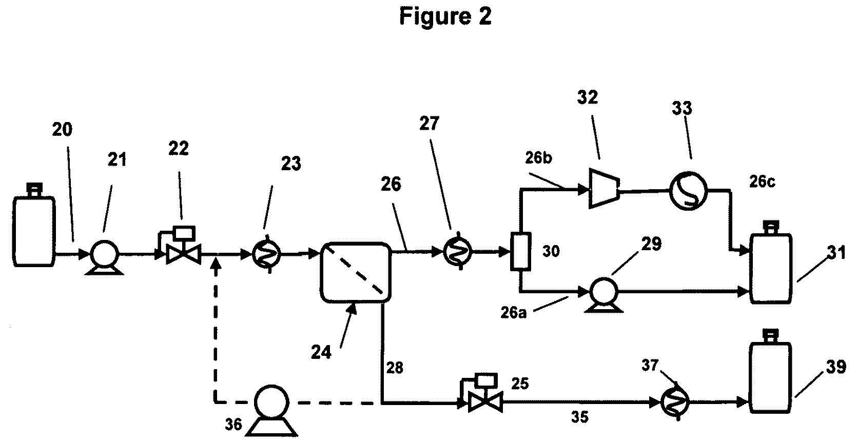
[0026]A simplified process schematic of the apparatus used in this example is provided in FIG. 2. A conventional gasoline feed (20) was pressurized by pump (21) to obtain the desired feed pressure. Feed flow was controlled by a mass flow control valve (22). The feed was heated to the desired temperature by means of a heat exchanger (23) by contacting against a circulating hot ethylene glycol-water mixture, for this example, typically maintained at 120° C. Alternatively, a silicone oil bath was used to obtain gasoline feed temperatures up to about 160° C. The preheated feed is substantially vapor upon delivery into the membrane module (24). Backpressure on the membrane was controlled by means of a pressure regulator (25) operating on the retentate stream (28) thereby providing the desired operating pressure Pf. The permeate (26) was recovered under vacuum provided by a vacuum pump (32). The permeate vapor was cooled by means of heat exchanger (27) to about 30° C. The “heavy” permeate...

example 3

[0027]For this embodiment, a polymer coated ceramic monolith was constructed in the following manner:

[0028]A solution of poly(ethylene adipate) “PEA,” pyromellitic dianhydride “PMOA,” 4,4′-methylene bis(2 chloroaniline) and 1,2,5,6-diepoxycyclo octane “DECO” was mixed with equal amounts of DMF and acetone to create an approximate 2.0 wt % polymer solution. The final molar ratios of the components were nominally 1-PEA2000 / 2-PMDA / 1-MOCA / 2-DECO. The solution was maintained at room temperature or lower after adding DECO. The solution was used to coat a porous ceramic monolith by drawing the liquid polymer into the porous surface of the monolith. The coated monolith was caused to form a polymer film of the composition described in U.S. Pat. No. 5,670,052 on the surfaces, including the interior surfaces, of the porous monolith, forming a polymer coating substantially free of voids and holes, having a surface area of about 0.1 m2.

[0029]The membrane was used in the simplified process and ap...


PUM

PropertyMeasurementUnit
temperature Tfaaaaaaaaaa
boiling pointaaaaaaaaaa

Abstract

The present invention pertains to a process for the separation of aromatics from a feed stream, including aromatics and non-aromatics by selectively permeating the aromatics through a membrane comprising feeding a mixed phase vapor-liquid feed to a membrane wherein said liquid phase preferentially wets the surface of the membrane.

Description

[0001]This Application claims the benefit of U.S. Provisional Application No. 60 / 830,614 filed Jul. 14, 2006.BACKGROUND OF THE INVENTION[0002]The present invention relates to the membrane separation of higher boiling point components from mixtures with a wide range of boiling points. In particular, the present invention is a membrane and process to separate aromatics from gasoline, or similar wide-boiling mixtures, such as petroleum naphtha.[0003]Pervaporation is a well-known membrane process. Pervaporation has been and is being considered for recovery of aromatics from refinery streams. A multicomponent liquid feed may be separated based on a selective solution-diffusion mechanism, with the permeate removed as a vapor. A vacuum is typically maintained on the permeate side of the membrane to facilitate permeation. Pervaporation is an endothermic process. Heat input is required to maintain the pervaporation process. Typically, the feed to the pervaporation process is preheated to tem...

Claims


Application Information

Patent Timeline
Patent Type & Authority Patents(United States)
IPC IPC(8): B01D15/00B01D53/22C07C7/144
CPCB01D61/362B01D69/10B01D71/64B01D71/80C10G31/11B01D2311/04B01D2311/10B01D2311/14B01D69/108B01D71/642
Inventor PARTRIDGE, RANDALL D.WEISSMAN, WALTERKAUL, BAL K.SABOTTKE, CRAIG Y.BHATIA, SANJAY K.
Owner EXXON RES & ENG CO
Why Eureka
Try Eureka