Reactor and process for the continuous production of hydrogen based on steam oxidation of molten iron

a technology of steam oxidation and reactor, which is applied in the direction of carbon monoxide, non-metallic elements, inorganic chemistry, etc., can solve the problems of increasing gas prices, increasing gas prices, and significant add-ons to plant costs, and achieves low hydrogen conten

Inactive Publication Date: 2011-03-29
AVAILABLE ENERGY CORP
View PDF21 Cites 35 Cited by
  • Summary
  • Abstract
  • Description
  • Claims
  • Application Information

AI Technical Summary

Benefits of technology

[0017]It is therefore an object of the invention to provide a hydrogen production process that overcomes the disadvantage discussed above by providing a process for continuous and controlled hydrogen production from a variety of carbonaceous materials, including beneficiated coals that have low hydrogen content, and that produces a pure hydrogen stream and a pure stream of CO2 suitable for capture and sequestration. In addition, the process, which may be implemented as a two, three, or four compartment reactor system, provides opportunities for removing contaminants sourced from the carbon containing feedstock such as sulfur and phosphorous.
[0018]The present invention also improves the availability of the hydrogen production process over that of conventional gasification. By providing an inventory of iron units, to provide a source of iron in the event that liquid iron is temporarily unavailable to the hydrogen-producing reactor from the reduction part of the process the steam oxidation reactor can produce hydrogen as a stand-alone process. In this event iron can act as transportable chemical hydride, which in solid form can be transported to the hydrogen plant from an external resource and supplied to the steam oxidation reactor or a purpose-built “back up” steam oxidation reactor by a supplementary melting unit in the process. The iron oxide produced can be stored, shipped to an iron oxide reduction facility or used at the HPPP site when the temporary unavailability of HPPP equipment is over.
[0019]In the case where an alternative hydrogen production technology is used, this above mentioned feature of the invention may serve as a method to increase the availability of the alternative hydrogen production process.
[0021]In cases where decarbonization does not occur in a separate zone the decarbonization may occur in the same zone as the reduction process by stopping the reduction process or the steam oxidation compartment is modified or built of sufficient capacity to allow for concurrent decarbonization and steam oxidation of iron. The use of a separate reactor will result in iron having a lower carbon concentration and hence higher purity, and hence higher gas purities coming out of the oxidation reactor as well as higher steam conversion efficiencies which will lower operating costs, however it may involve building another furnace reactor and hence a significant increase in capital cost.
[0022]The decision on where decarbonization occurs, whether it occurs in a separate reactor or in the reduction reactor or the oxidation reactor or partial decarbonization in both, depends in part on the purity of hydrogen needed, the hydrogen production rate, which determines scale and plant equipment cost, the nature of the carbonaceous material being gasified, and, in the case of the steam oxidation reactor, the ability to preferentially generate iron oxide as compared with carbon monoxide based on the relative concentration of dissolved carbon in the iron-carbon solution and other processing conditions. Additional injection of an oxidant(s) in this vessel, such as air, oxygen, steam or carbon dioxide (though preferably oxygen), can enhance the rate of formation of iron oxide. In certain cases or oxidant mixtures, this could add heat to the steam oxidation reactor.
[0032]b) a means for processing the carbon saturated molten iron to reduce a carbon concentration in the carbon saturated molten iron in the second compartment;

Problems solved by technology

At the same time as this demand increase is occurring, “conventional” sources of natural gas in North America are being depleted, tightening the supply of gas and raising gas prices.
The gas separation process required to extract hydrogen from the output of the gasifier, which is a mixture mostly of CO2, CO and hydrogen, is energy intensive and is a significant adder to the plant cost.
The interaction of these variables can result in a variation in hydrogen production rate, resulting in the need for process buffers and storage to average out these variations when connected to down stream processes, making it less suitable than SMR for the controlled delivery of hydrogen particularly for very large hydrogen demands.
The difficulty with these processes is the rate of reaction and hence hydrogen production rate is very low.
Also the steam oxidation of solid iron is a surface reaction; hence the volumetric efficiency of the reactor is low which is a drawback particularly for large production capacities.
Controlling the rate of hydrogen production is also problematic for powder systems as it is difficult to achieve a consistent steam oxidation rate in a large fixed bed reactor because steam-oxidation, and hence hydrogen production, occurs at the surface, and the amount of reactant surface is changing and hence the amount of steam needed to achieve a certain hydrogen production rate changes.
As a consequence a minimal amount of the material is ejected from the bath resulting in less slag sticking to the walls of the containment vessel above the molten metal bath, which can result in a constriction impeding materials flowing in and out of the reactor.
The purity could be an issue.

Method used


Image

  • Reactor and process for the continuous production of hydrogen based on steam oxidation of molten iron
  • Reactor and process for the continuous production of hydrogen based on steam oxidation of molten iron
  • Reactor and process for the continuous production of hydrogen based on steam oxidation of molten iron

Examples


first embodiment

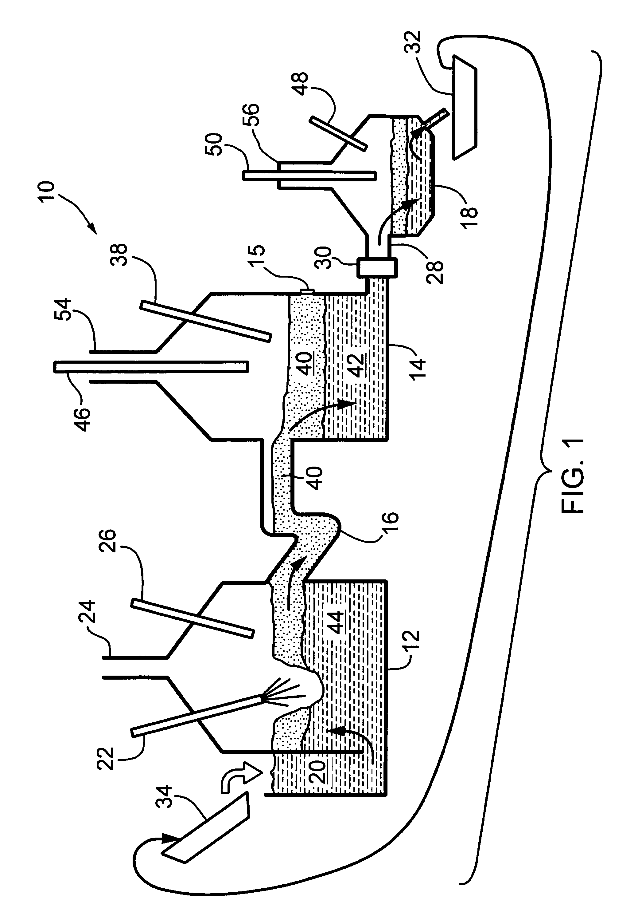
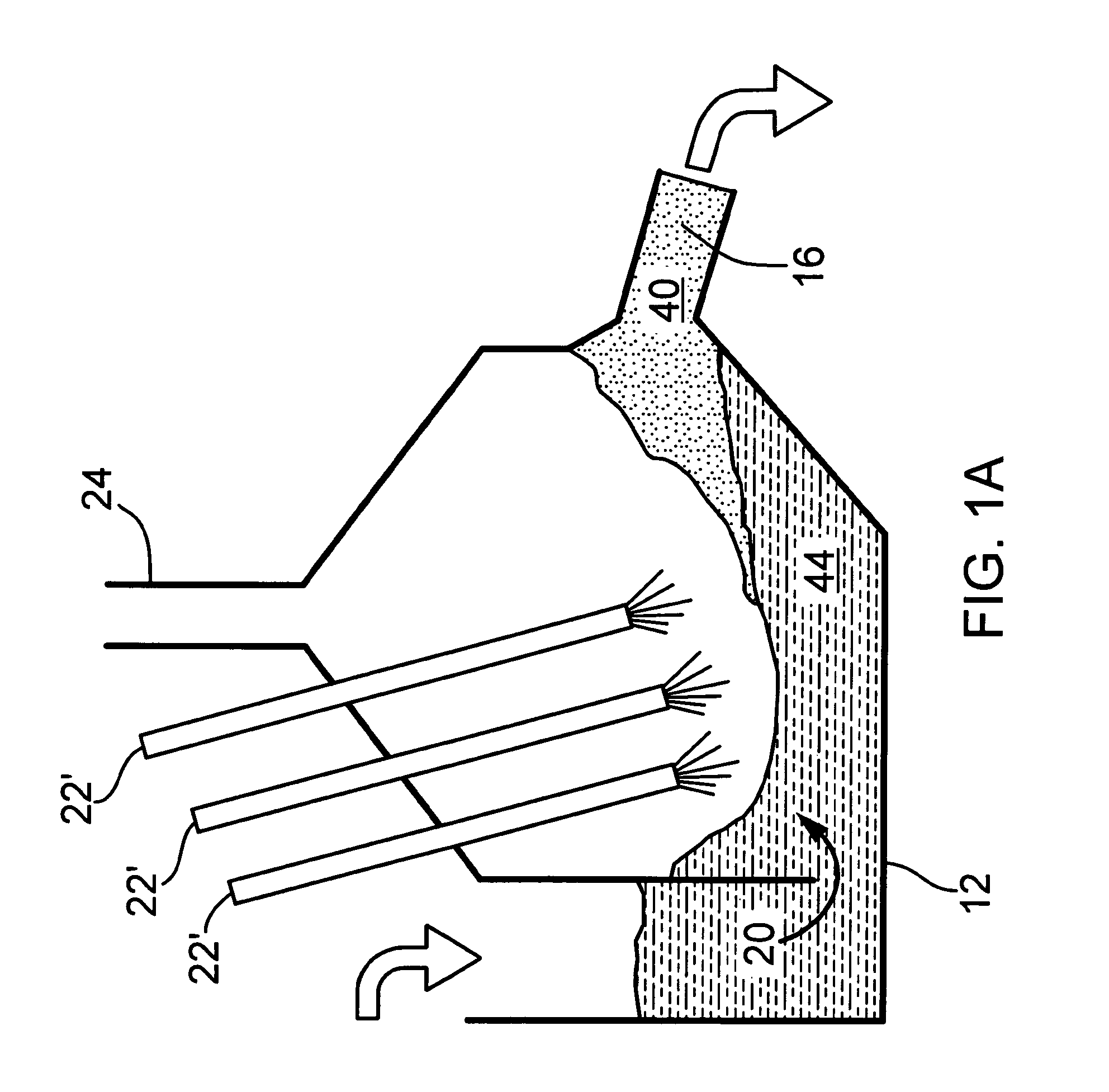
[0060]The method disclosed above using three (3) vessels can be carried out using an apparatus such as that shown in FIG. 1. Referring first to FIG. 1, a first embodiment the apparatus for producing hydrogen is shown generally at 10 and includes a first vessel 12 and a second vessel 14 with the interiors of the vessels 12 and 14 connected by a passageway 16 with the vessels and passageway made of a material capable of withstanding the temperatures of molten iron, molten iron oxide and other materials contained therein.

[0061]A third vessel 18 is connected to vessel 14 by a conduit 28 and a valve 30 may or may not be present. Iron regenerated in the third vessel is emptied into a ladle(s) 32 and recycled back to vessel 12. Valve 30 is not needed in the case where the system is configured such that ladle(s) 32 continuously removing metal or alloy, but it is present when slag layer 40 is periodically tapped (unless it is drained through location of valve 30 during periodic tap). Vessel ...

embodiment 80

[0093]In another embodiment of the hydrogen production system, any iron lost in the process may be added on a continuous basis by injecting it into the vessel 12 or, on a batch basis using a separate melter such as the arc furnace, 82 shown in the embodiment 80 in FIG. 2, where the molten iron enters the hydrogen generation process through the steam oxidation reactor vessel 12 as seen in FIG. 2. In embodiments using a batch iron feed to replenish the molten metal, the accumulation of ash in the reduction reactor vessel 14 can be removed by dumping large volumes of slag that will allow longer uninterrupted operation when iron oxide reduction is taking place. To manage the large volumes of slag the reactor vessel 14 may be designed to tilt on a pivot to empty its contents or one or more tap holes 15 could be used.

[0094]It will be understood that the process described herein may be implemented with more than the reactor vessels 12, 14 and 18 described above. For example an embodiment o...

embodiment 160

[0107]The process performed using the system 100 in FIG. 3 can be simplified by dropping the two separate decarbonizaton reactor compartments as shown in the embodiment 160 shown in FIG. 3A and combining either the oxidation and decarbonization steps in the steam oxidation reactor compartment 106 or inject an oxidant through 120 into the reduction reactor compartment 108 after the carbon injection through 120 is stopped and before the alloy is drained from the reactor compartment 108. Combining decarbonization through steam oxidation of carbon in the iron and steam oxidation of the iron has the disadvantage of lowering the steam efficiency in the steam oxidation reaction and relies on the volume of iron in the steam oxidation being large enough to dilute the concentration of carbon in iron low enough so that the steam iron oxidation process can achieve the required reaction rate and hence hydrogen production rate.

[0108]In apparatus 260 shown in FIG. 3B the decarbonization process is...


PUM

PropertyMeasurementUnit
temperatureaaaaaaaaaa
thickaaaaaaaaaa
concentrationaaaaaaaaaa

Abstract

The present invention provides a reactor and gasification process for the continuous controlled production of hydrogen (H2) and a by-product synthesis gas (mixture of CO+H2+CO2), such a process called a hydrogen priority poly-generation process (HPPP). The reactor uses a circulating molten iron process, which is capable of gasifying a variety of carbonaceous materials including low rank coals and biomass. The process employs an iron steam oxidation-reduction cycle in a multi-chamber reactor including a multi-vessel reactor system, where in one compartment or vessel hydrogen is produced by steam oxidation of molten iron; and in a second compartment or vessel the iron is regenerated by carbon reduction of molten iron oxide thereby producing a by-product synthesis gas (CO+H2+CO2), and excess heat which can be used to produce steam, and in a third step the iron is purified before being returned to the steam oxidation step in the process. An embodiment of this process uses low rank coals having high ash levels in a reactor, which is designed to continuously extract ash from the molten iron bath. A second embodiment uses low ash carbon materials such as highly beneficiated coals in a simpler process that produces pure streams of hydrogen and CO.

Description

CROSS REFERENCE TO RELATED U.S. PATENT APPLICATIONS[0001]This patent application relates to U.S. utility patent application Ser. No. 60 / 879,010 filed on Jan. 8, 2007 entitled REACTOR AND PROCESS FOR THE CONTINUOUS PRODUCTION OF HYDROGEN BASED ON STEAM OXIDATION OF MOLTEN IRON, filed in English, which is incorporated herein in its entirety by reference.FIELD OF THE INVENTION[0002]The present invention relates to a method and apparatus for hydrogen production, the hydrogen priority polygeneration process (HPPP), that combines steam oxidation of molten iron and carbon reduction of molten iron oxide to provide a continuous controlled source of hydrogen and a separate by-product synthesis gas.BACKGROUND OF THE INVENTION[0003]The majority means of hydrogen production today uses steam methane reforming of natural gas (SMR). In North America and in particular Canada, the demand for hydrogen is expected to increase at rates significantly higher than general economic growth because of demands...

Claims


Application Information

Patent Timeline
Patent Type & Authority Patents(United States)
IPC IPC(8): C01B3/10C01B32/40
CPCC01B3/105Y02E60/36
Inventor MCLEAN, LESLIE C.FAIRLIE, MATTHEW JAMESSTUART, ANDREW T. B.
Owner AVAILABLE ENERGY CORP
Why Eureka
Try Eureka