Implantable electrode

a technology of implantable electrodes and electrodes, applied in the field of implantable electrodes, can solve the problems of mechanical processing (during manufacture), electrical contact in such a device has proven problematic, and the impedance rise, so as to improve the charge capacitance, reduce the irritation of tissue, and ensure the effect of stability

Active Publication Date: 2013-02-19
HERAEUS MEDICAL COMPONENTS LLC
View PDF19 Cites 7 Cited by
  • Summary
  • Abstract
  • Description
  • Claims
  • Application Information

AI Technical Summary

Benefits of technology

[0011]The present inventor has appreciated that the porous conducting interface of an implantable electrode can be adapted to improve its charge capacitance. Further advantage may be provided if the porous conducting interface is biocompatible, thereby causing minimal tissue irritations after implantation, and also has an anti-inflammatory effect. Furthermore, the titanium nitride or other material should be resistant to corrosion, particularly under pulse regimes where hydroxide is generated.
[0012]The present invention provides thin conducting coatings which can be deposited on high surface area materials such as titanium nitride and which (i) possess tissue biocompatibility, (ii) can be anti-inflammatory, (iii) can provide stability to body fluids and prevent base generation, (iv) can retain or enhance capacitance and have low impedance characteristics, (v) can strongly adhere under in vivo pulsing conditions.
[0013]This invention can provide strongly adherent thin films based on poly(pyrroles) which can be grown upon titanium nitride and related nitride, carbide or oxide materials and which may possess a high degree of biocompatibility and other desirable properties such as those cited above.

Problems solved by technology

However, mechanical processing (during manufacture) and electrical contacting in such a device have proven problematic.
While the physical properties of the titanium nitride are substantially unchanged in stimulation electrodes with a titanium nitride layer which is used as the cathode, this is not the case with use as an anode.
The attack by OH-ions leads to the formation of oxide layers, which cause a rise of impedance and therewith also a rise of the threshold voltage.

Method used


Image

  • Implantable electrode
  • Implantable electrode

Examples


Embodiment Construction

Coating of Titanium Nitride Substrates

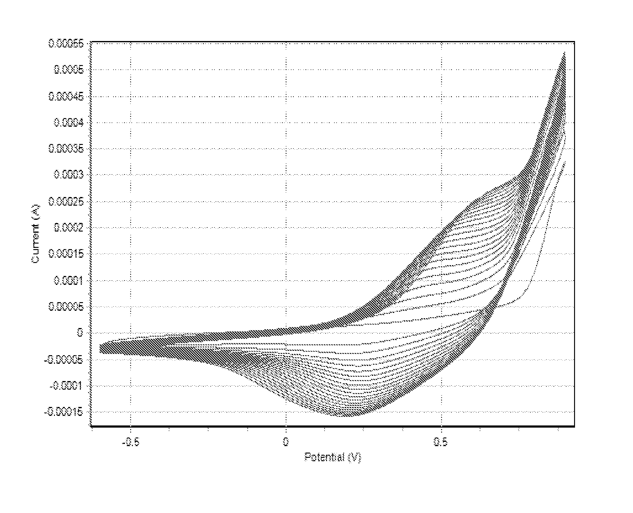
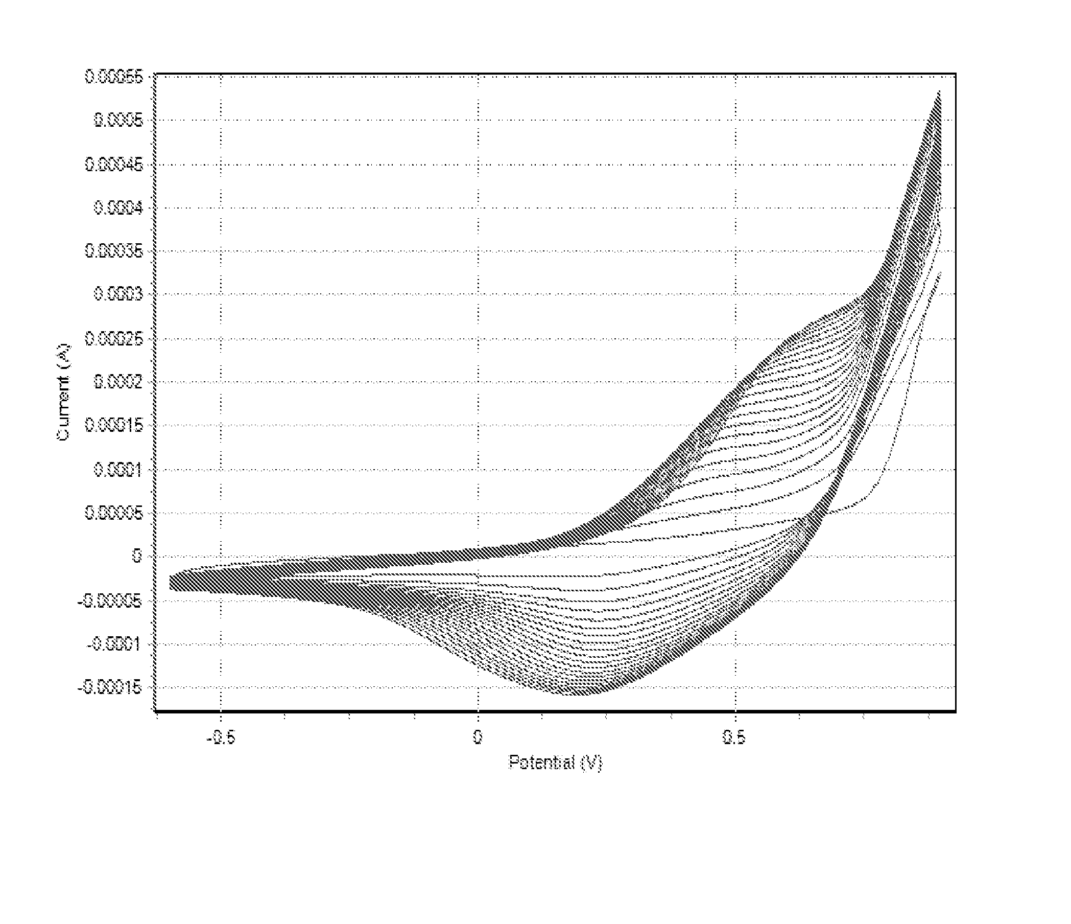
[0155]Electrochemical procedures were used to deposit pyrrole polymers onto porous TiN electrodes. The electrodes were dome shaped with approximate dimensions: height 1 mm, diameter 1.2 mm, area 4.3 mm2. Electrochemical coating upon two types of TiN deposit were established. The two types of TiN electrodes have TiN layers formed by PACT (plasma assisted coating technology) TiN and HSA (high surface area) TiN.

[0156]Electrodes were first cleaned by sonicating in 1% Micro90 solution (aq) (a cleaning solution) for 1 minute then washed in a flowing stream of DI water (deionized water) for 30 seconds, then blown dry with nitrogen and used immediately. Electrodeposition was performed in a one compartment cell with lead as working electrode, Ag / Ag+ (non aqueous) as reference electrode and stainless steel as counter electrode (25×75 mm) looped around inner surface of cell. Electrolyte solution was degassed with bubbling nitrogen for 30 minutes and kept u...


PUM

PropertyMeasurementUnit
thicknessaaaaaaaaaa
thicknessaaaaaaaaaa
thicknessaaaaaaaaaa

Abstract

An implantable electrode, for an implantable tissue stimulator, has an electrically conductive porous material comprising metal carbide, metal nitride, metal carbonitride, metal oxide or metal oxynitride and one or more coating layers on a surface thereof. The coating layer or at least one of the coating layers, is for contact with body tissue when the electrode is implanted. Each coating layer is an electrically conductive layer of polymer having a polypyrrole polymeric backbone or polythiophene polymeric backbone. The coating layer or layers are formed in situ by electropolymerisation. The polypyrrole or polythiophene may be substituted. The coating layer or layers can provide high charge storage capacitance and a fast discharging profile, as well as biocompatibility.

Description

FIELD OF THE INVENTION[0001]This invention relates to an implantable electrode suitable for contact with body tissue when implanted in a human or other animal, especially a mammal, and to an implantable tissue stimulator having such an electrode, as well as to a method of making such an electrode.BACKGROUND OF THE INVENTION[0002]In most cases, implantable stimulation or stimulating electrodes, for example for heart pacemakers, consist of an electrode body having an insulated cable lead and an electrode head for the transmission of the stimulation pulses, i.e. the active or effective area of the electrode.[0003]Such electrode materials should be compatible with the body, i.e. the formation of connective tissue layers should be very low if it is not suppressed altogether; in any case, the thickness of connective tissue should remain below 100 μm. The stimulation threshold, further, should be as constant as possible. Furthermore, a high double layer capacitance should form at the phase...

Claims


Application Information

Patent Timeline
Patent Type & Authority Patents(United States)
IPC IPC(8): A61N1/00
CPCA61N1/056A61N1/0565C09D5/24C09D5/4476C25D7/00C25D13/04A61N1/362C08G2261/3221C08G2261/3223A61N1/3629
Inventor PICKETT, CHRISTOPHER JOHN
Owner HERAEUS MEDICAL COMPONENTS LLC
Why Eureka
Try Eureka