
Non-aqueous heat transfer fluid and use thereof

a heat transfer fluid and non-aqueous technology, applied in the direction of lighting and heating apparatus, corrosion prevention, chemical equipment and processes, etc., can solve the problems of adverse health effects of heat transfer fluid exposure, contamination of the environment, and human and other mammals' health hazards, so as to reduce the stress on engine system components, reduce the loss of coolant to the environment, and reduce overheating.

Inactive Publication Date: 2013-03-12
EVANS COOLING SYST INC
View PDF46 Cites 18 Cited by
  • Summary
  • Abstract
  • Description
  • Claims
  • Application Information

AI Technical Summary

Benefits of technology

The present invention relates to non-aqueous heat transfer fluids that can be used as engine coolants in extreme temperatures and can also be used in cooling systems designed for use with water-based coolants. These fluids are able to operate at lower pressures, reducing stress on engine system components and promoting longevity of pump seals, hoses, and system components. Additionally, these fluids do not cause cylinder liner cavitation, making them suitable for heavy-duty engines without the need for separate formulations. The absence of water in the fluids also eliminates the need for additives to control reactions and reduces contamination. These fluids are also suitable for use in heat exchange systems for cooling electric or electronic components and can be used without the need for special double walls to prevent contamination.

Problems solved by technology

Most heat transfer fluids that are currently used contain water mixed with ethylene glycol (EG), a hazardous substance that can cause environmental contamination as a result of improper disposal.
These fluids can cause dangerous health effects upon humans and other mammals if they are ingested.
In addition, adverse health effects can occur due to exposure to used heat transfer fluids as a result of contamination by elemental heavy metal precipitates and toxic inhibitors that are added to prevent water related reactions.
It is estimated that a significant percentage of the concentrates are disposed of improperly, resulting in contamination of the environment.
Improper disposal by consumers is a major cause of this environmental contamination.
Another major source of environmental contamination is leakage, spills and overflows from heavy duty vehicles.
Experience with heavy duty vehicles shows that it is common to lose 10% of the engine heat transfer fluid volume after every 12,000 to 18,000 miles of operation due to leaks in the system components, such as the water pump, hose clamps or radiator core.
A heat transfer fluid leak rate of one drop per minute is likely to go unnoticed, but can in total add up to a significant loss.
Overflows occur due to overheating or when an engine cooling system is overfilled.
When an engine cooling system is overfilled, operation of the engine heats the heat transfer fluid, causing expansion of the fluid that cannot be contained in the system.
However, before biodegradation occurs, these spills and leaks can present a toxic danger to pets and wildlife.
The repeated high frequency formation and collapse of coolant vapor attacks the surface of the liner, eroding small amounts of iron.
By comparison, the use of sodium nitrite is not necessary or desirable in light duty engines.
The complexity of balancing various water to EG (or PG) ratios and different additive formulations can result in improper freeze protection and clogged radiators and heater cores when the engine coolant is misformulated.
As discussed further below, many of these problems are a result of the need for a substantial water fraction in these engine coolants.
The longer coolant service requirement results in the need to periodically replenish the inhibitors in heavy-duty engine coolants.
Supplemental coolant additives must be chemically balanced with the coolant volume, which can be difficult and costly to control properly.
Improper balancing of additives can result in severe damage to cooling system components and the engine.
If the concentration of the supplemental coolant additives in the coolant is too low, corrosion and cavitation damage to the engine and cooling system components can occur.
If, on the other hand, the concentration of supplemental additives is too high, additives can precipitate from the coolant solution and clog radiator and heater cores.
A further concern with supplemental coolant additives is that they may, under certain conditions, be difficult to properly dissolve in the engine coolant.
If the supplemental additives do not completely dissolve, they may be a source of additional clogging problems in the engine.
A major disadvantage of using EG as a freezing point depressant for engine coolants is its high toxicity to humans and other mammals if ingested.
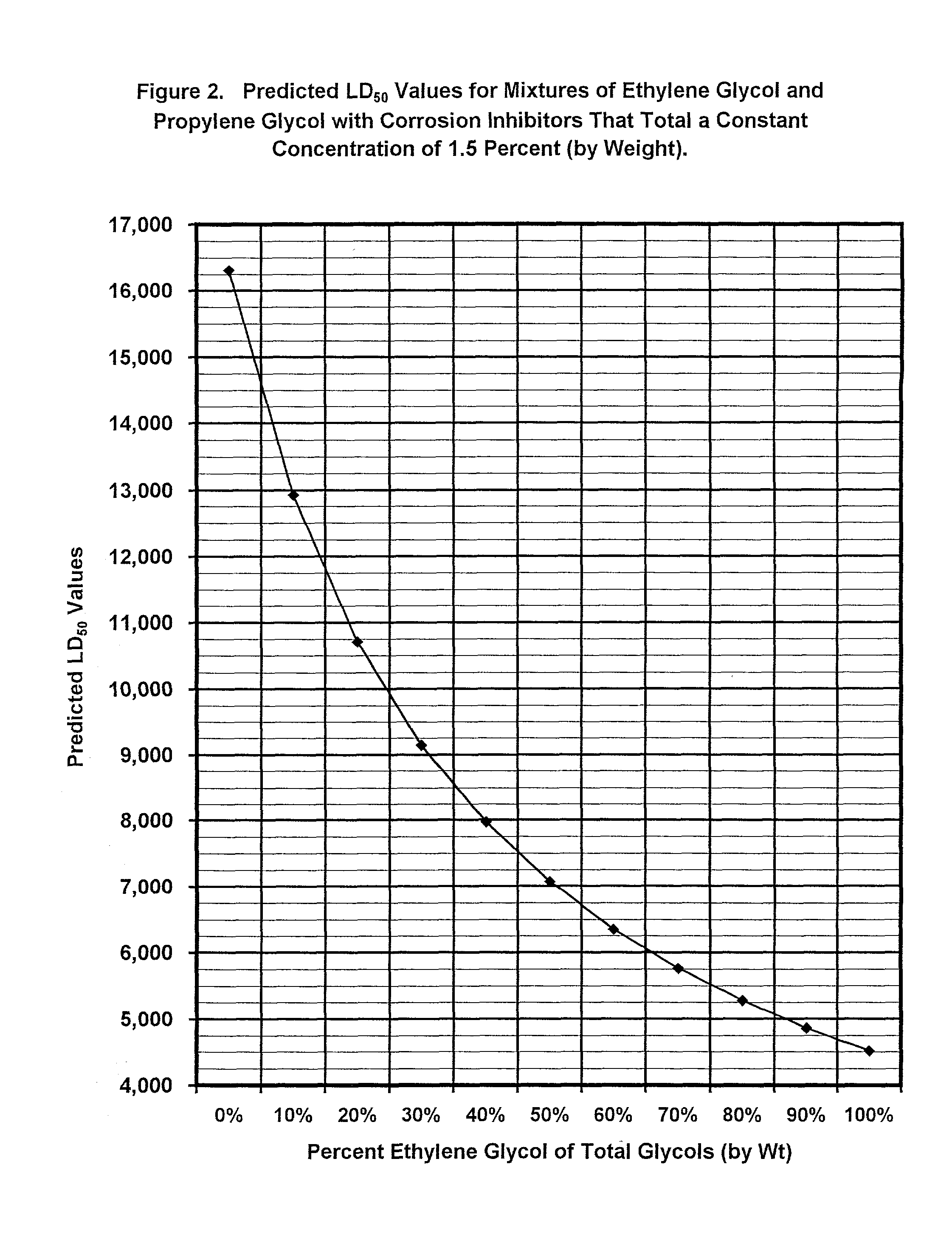
Because EG has an LD50 value of 4,700 mg / kg, EG is considered hazardous by this rating system.
The toxicity associated with EG is caused by the metabolites of EG, some of which are toxic.
Consequently, EG is classified by many regulatory authorities as a dangerous material.
One impediment to more widespread usage of PG as a base fluid for antifreeze concentrates is its relatively high cost as compared to EG.
However, because some of the required additives are not readily soluble in either EG or PG, water is added to all conventional concentrate mixtures.
Although three to five percent water is intentionally added to EG and PG concentrates to dissolve water soluble additives, addition of water alone is not effective over long periods of time to maintain the additives in solution.
This can be a severe problem for engines used in stationary emergency pumps and generators as well as military and other limited use engines.
The water added to concentrates to form an engine coolant can also cause formation of potentially hazardous products.
As a result, precipitates of heavy metals, such as lead and copper, can become suspended in the circulating coolant in the engine.
Even with the addition of additives to control these reactions, aluminum is constantly lost to the conventional engine coolants containing approximately 50 / 50 mixtures of EG and water.
Corrosion of metal surfaces in engine cooling systems using conventional glycol / water coolants is also caused by the formation of organic acids in the coolant, such as pyruvic acid, lactic acid, formic acid, and acetic acid.
Moreover, the inhibitors must not be used in excess concentration (in an attempt to extend the depletion time) because that can cause damage to system components due to precipitation resulting in plugging of radiator and heater core tubes.
In addition, silicates, silicones, borates and phosphates are chemically abrasive and can erode heat exchanger tubes and pump impellers.
In addition, these water soluble additives require heat, extreme agitation, and extensive time for the water to react and cause the additives to dissolve.
These requirements add significant cost and complexity to the formulation and packaging of antifreeze concentrates.
The energy costs and time required for blending, before packaging, are a major factor in the processing costs.
Also, because many of these additives may interfere with each other and cause an incomplete solution and failure of the formulation process, the formulating process must be monitored constantly to assure a proper blend.
In addition, some of the additives themselves, e.g., borates, phosphates, and nitrites, are considered toxic.
Thus, not only do all known coolant concentrate formulations include additives that require heat, extreme agitation and extensive time for the water to react and cause the additives to dissolve, but the additives themselves are sometimes toxic.
Further, the additives require complex balancing which accommodates the prevention of interference between the additives, while also preventing the excessive presence of any one additive in the coolant.

Method used


Image

  • Non-aqueous heat transfer fluid and use thereof
  • Non-aqueous heat transfer fluid and use thereof
  • Non-aqueous heat transfer fluid and use thereof

Examples


example 1

[0095]This corrosion test was performed using the test procedure set forth in ASTM #D-1384 (Modified). Six specimens, typical of metals present in an engine coolant system, were totally immersed in the test coolants contained in glassware. Coolant “A” was a non-aqueous heat transfer fluid of the present invention in which the polyhydric alcohol portion was 100 percent PG. Coolant “B” was a conventional engine coolant formulation comprised of an EG based antifreeze concentrate mixed with water.

[0096]In the ASTM test procedure, the coolant is aerated by bubbling air up through the glassware, and maintained at a test temperature of 190° F. (88° C.) for 336 hours. This procedure was modified to more accurately reflect the conditions that would be experienced by the metals in an engine coolant system in use. The tests were conducted at a control temperature of 215° F. (101.6° C.) to simulate severe duty use. Coolant “A” was tested without aeration being applied in order to more closely a...

example 2

[0102]This corrosion test was conducted to determine the amount of corrosion of cast aluminum or magnesium alloys in engine coolants under heat rejecting conditions. A cast aluminum alloy specimen, typical of that used for engine cylinder heads or blocks, was exposed to test engine coolant solutions. Coolant “A” was a non-aqueous coolant of the present invention with 100 percent PG. To simulate the operating conditions of a coolant system using a non-aqueous coolant, the test using Coolant “A” was conducted at a temperature of 275° F. (135° C.) and a pressure of 2 psig (13.79 kPa), which is slightly above ambient pressure. Test Coolant “B” contained an ASTM prescribed corrosive water used to make up the water fraction of a 50 / 50 EG / water coolant. The test conditions for Coolant B, which simulate the conditions in an aqueous coolant engine cooling system, were a temperature of 275° F. (135° C.) and a pressure of 28 psig (193 kPa).

[0103]In each test, a heat flux was established throug...

example 3

Field Test

[0105]A 3.8L V-6 engine was operated over the road for a test period of 55,000 miles (88,511.5 km). The engine cooling system in the vehicle was configured as described in U.S. Pat. No. 5,031,579. Coolant “A” was identical to the non-aqueous coolant described in Example 1 above. There was no draining or replacing of the coolant during the test period. A metal specimen bundle was placed within the full flow of the engine coolant stream (lower hose) and was kept submerged in the coolant at all times. Performance of the test coolant's ability to inhibit metal corrosion was evaluated by comparing the results in milligrams lost of the specimen at the end of the test period to ASTM test standards. The results were as follows:

[0106]

Δ WT (mg)METALCOOLANT “A”ASTM STD.Cast Iron−2.8−10Aluminum+0.2−30Steel−1.1−10Copper−1.3−10Solder−3.7−30Brass−0.9−10pH at start+7.1NApH at finish+6.9NA

Method of Manufacture

[0107]The non-aqueous heat transfer fluid of the present invention may be manufac...


PUM

PropertyMeasurementUnit
Fractionaaaaaaaaaa
Fractionaaaaaaaaaa
Percent by massaaaaaaaaaa

Abstract

A non-aqueous, reduced toxicity polyhydric alcohol based heat transfer fluid is provided comprised of at least one polyhydric alcohol that acts as an ADH enzyme inhibitor, such as for example propylene glycol, thereby reducing the toxicity of ethylene glycol if ethylene glycol. The heat transfer fluid may also include corrosion inhibitors that are soluble in the polyhydric alcohols used for the heat transfer fluid. The heat transfer fluid may be used as a coolant in internal combustion engines such as automobile engines, a coolant for cooling electrical or electronic components, as a heat transfer fluid for solar energy heating systems, or a heat transfer fluid for maintaining temperatures in industrial processes. A low toxicity preparation fluid for absorbing water from heat exchange systems prior to installation of the heat transfer fluid is also provided that is comprised of ethylene glycol and at least one polyhydric alcohol, preferably propylene glycol, that acts as an ADH enzyme inhibitor.

Description

RELATED APPLICATIONS[0001]The present application is a continuation-in-part of patent application U.S. Ser. No. 09 / 910,497 filed on Jul. 19, 2001.FIELD OF THE INVENTION[0002]The present invention relates generally to a substantially non-aqueous, reduced toxicity heat transfer fluid for use in heat exchange systems such as a coolant for internal combustion engines, a coolant for electrical or electronic components, a heat transfer fluid for solar energy heating systems, or a heat transfer fluid for maintaining temperatures in industrial processes. The present invention also relates to a compatible reduced toxicity preparation fluid for absorbing residual water from heat exchange systems in preparation for installing the non-aqueous heat transfer fluid.BACKGROUND OF THE INVENTION[0003]Heat transfer fluids are used in a variety of applications. One common use of heat transfer fluids is as a coolant in internal combustion engines. Most heat transfer fluids that are currently used contai...

Claims


Application Information

Patent Timeline
IPC IPC(8): C09K5/10C09K5/20C09K5/08C23F11/08C23F11/12C23F11/14C23F11/18F28F19/00
CPCC09K5/10C09K5/20C23F11/08
Inventor EVANS, JOHN W.LIGHT, J. THOMAS
Owner EVANS COOLING SYST INC
Learn More