Method and apparatus for preparing specimens for microscopy

a microscopy and specimen technology, applied in the field of methods and apparatus for preparing specimens for microscope examination, can solve the problems of reactive ions, inability to effectively image using the secondary electron mode of an sem, and little or no topography

Active Publication Date: 2014-03-25
E A FISCHIONE INSTR
View PDF21 Cites 13 Cited by
  • Summary
  • Abstract
  • Description
  • Claims
  • Application Information

AI Technical Summary

Benefits of technology

[0031]In yet another alternative embodiment, the present invention relates to an apparatus for preparing a specimen for microscopy including a plasma generator for plasma cleaning the specimen, and an assembly for removing material from the specimen, such as by etching, wherein the plasma cleaning of the specimen and the removing of material from the specimen may be performed under continuous vacuum conditions. The assembly for removing the material such as by etching may comprise an ion source for directing an ion beam at the specimen. The apparatus may include a single chamber for processing the specimen or may include first and second chambers connected to one another through a vacuum valve. The apparatus may further include a specimen stage for holding the specimen that is tiltable and rotatable.

Problems solved by technology

When created, however, these cross-sections have little or no topography, and thus cannot be effectively imaged using the secondary electron mode of an SEM.
One problem with RIBE is that the reactive ions can also react with the materials of which the ion gun is constructed.
This causes corrosion and early wear-out of the gun.
Sample geometry becomes a limitation when trying to adapt IBE technology from TEM to SEM.
Many IBE devices are designed to only accommodate the consistent sample size of a TEM sample.
However, the sheath voltage of an ICP is generally much lower than the sheath voltage of a capacitive discharge, and so the ions generally exit the plasma with less speed, resulting in lower anisotropy.
If the specimen is made of a non-conducting insulating material, the impinging electrons of the SEM are not conducted away from the material and will accumulate on the surface of the specimen and cause charging effects that disturb the trajectories of subsequent beam electrons and reduce the quality of the image.
In resistive heating methods, the coating material is heated by placing it in contact with an electrical conductor, through which an electrical current is passed, causing heat.
The impact of the electrons impinging on the source material causes heat within the material.
By either method, heating the material causes thermal evaporation of the material.
One problem that adversely affects the quality of SEM analysis is hydrocarbon contamination of the specimen.
This contamination can occur as a result of poor operator handling techniques during the preparation process, such as touching the specimen with an ungloved hand.
Other contamination may result from subjecting the specimen to a preparation process that utilizes an oil diffusion pump or a turbomolecular pump backed by a vacuum pump that utilizes oil in its pumping path whereby backstreaming of oil will lead to contamination, the use of hydrocarbon based solvents and adhesives in the preparation process, storage or exposure of the specimen to ambient conditions, and repeated exposure to the SEM vacuum system which may contain oil vapor which has migrated up the electron optics column from a vacuum pump or has entered the chamber through its exposure to ambient conditions.
Furthermore, contamination of the specimen surface and of the target can have a detrimental effect on the quality of the coating deposited by a sputtering coating method.
Such contamination can lead to adhesion difficulties for the coating material, unevenness of the coating, and possibly the formation of unwanted inter-metallic species.
Contamination of the sputtering target can lead to the deposition of unwanted compound materials rather than the monatomic metallic species.
Moreover, a specimen may become contaminated when it is transferred in the ambient environment from one processing device to the next while being prepared for microscopy.
For example, a specimen may be so contaminated when transferred from a stand alone plasma cleaning device to a separate stand alone coating or ion milling device.
This will knock off unwanted contamination from the surface of the specimen.
Furthermore, sputtering of the specimen surface can lead to etching effects.
This also may result in etching of the specimen surface, particularly for softer materials.

Method used


Image

  • Method and apparatus for preparing specimens for microscopy
  • Method and apparatus for preparing specimens for microscopy
  • Method and apparatus for preparing specimens for microscopy

Examples


Embodiment Construction

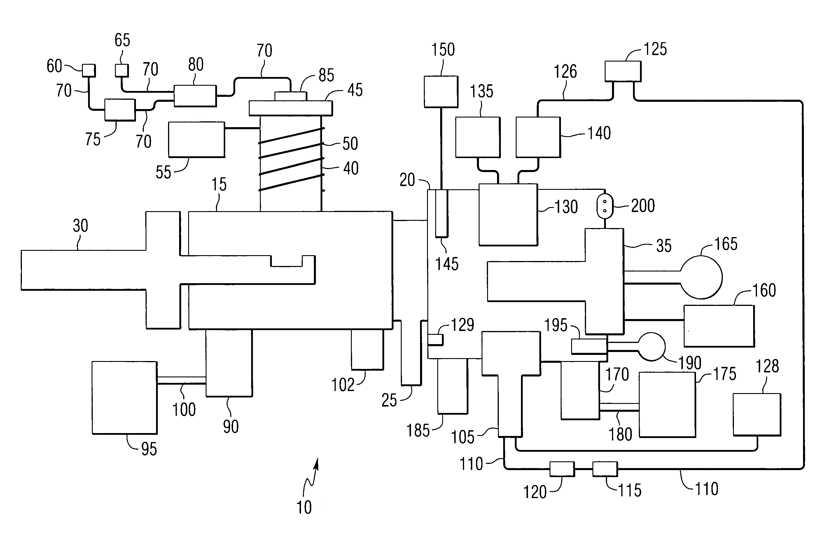
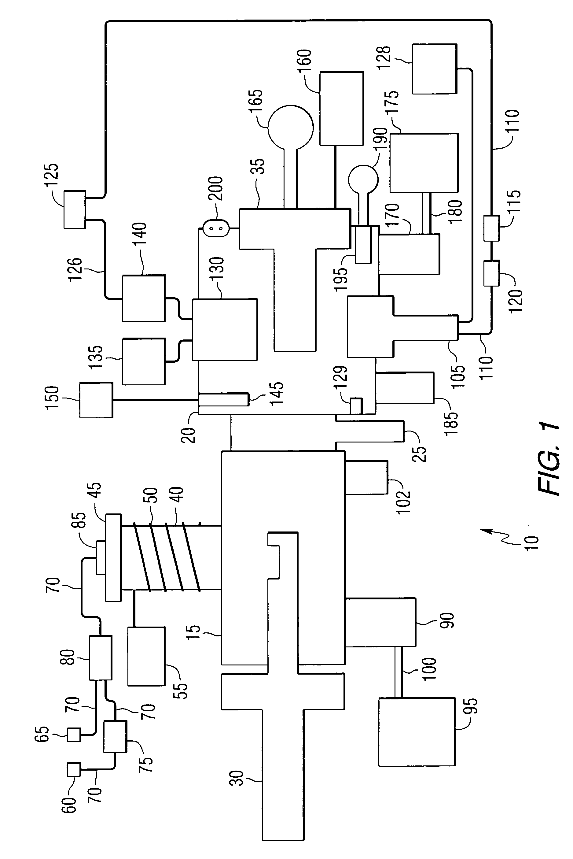
[0051]Referring to FIG. 1, a block diagram of plasma cleaning, etching and coating apparatus 10 according to a first embodiment of the present invention is shown in which specimens may be plasma cleaned, etched or coated alone or in any combination under a continuous vacuum state. Plasma cleaning, etching and coating apparatus 10 includes plasma chamber 15 made of, for example, stainless steel or aluminum, in which a specimen may be subjected to a plasma cleaning operation such as that described in Fischione, U.S. Pat. No. 5,633,502. Plasma cleaning, etching and coating apparatus 10 also includes etching and coating chamber 20 made of, for example, stainless steel or aluminum, in which a specimen may be etched, coated, or both. Plasma chamber 15 and etching and coating chamber 20 are connected by vacuum valve 25, which may be manually or automatically actuated. Preferably, vacuum valve 25 is provided with interlocking capability to prevent inadvertent opening of vacuum valve 25 if p...


PUM

PropertyMeasurementUnit
heightaaaaaaaaaa
frequencyaaaaaaaaaa
frequencyaaaaaaaaaa

Abstract

An apparatus for preparing specimens for microscopy including equipment for providing two or more of each of the following specimen processing activities under continuous vacuum conditions: plasma cleaning the specimen, ion beam or reactive ion beam etching the specimen, plasma etching the specimen and coating the specimen with a conductive material. Also, an apparatus and method for detecting a position of a surface of the specimen in a processing chamber, wherein the detected position is used to automatically move the specimen to appropriate locations for subsequent processing.

Description

CROSS REFERENCE TO RELATED APPLICATION[0001]This application claims the benefit of U.S. Provisional Application No. 60 / 400,932 filed on Aug. 2, 2002.FIELD OF THE INVENTION[0002]The present invention relates to a method and apparatus for preparing specimens for examination in a microscope, such as a scanning electron microscope, and in particular, an apparatus that includes various specimen preparation functionality under continuous vacuum conditions.BACKGROUND OF THE INVENTION[0003]A scanning electron microscope, or SEM, uses electrons to form an image of a specimen. A beam of electrons is produced in the SEM by an electron gun, e.g., by heating a filament. The electron beam follows a path through the column of the microscope and is focused and directed toward the specimen to be imaged using a series of electromagnetic lenses and apertures. When the electron beam strikes the specimen, a number of signals are generated. The different signals can be used to generate different types of...

Claims


Application Information

Patent Timeline
Patent Type & Authority Patents(United States)
IPC IPC(8): H01J37/32H05H1/00H01J37/20H01J37/305H01J37/18C23C14/34G01N1/32
CPCH01J37/20H01J37/3056H01J2237/335H01J37/185H01J2237/3174G01N1/32H01J37/32082H01J2237/1825G01N1/28G01B11/14
Inventor FISCHIONE, PAUL E.ROBINS, ALAN C.SMITH, DAVID W.CERCHIARA, ROCCO R.MATESA, JR., JOSEPH M.
Owner E A FISCHIONE INSTR
Why Eureka
Try Eureka