High surface area and low structure carbon blacks for energy storage applications

a technology of carbon black and energy storage, applied in the field of carbon black, can solve the problems of limiting the power parameters of partially discharged batteries, affecting the performance of the battery, and gaining both low esr and high volumetric capacitance from the same material, and achieves high electrode density, high packing density, and low resistance.

Active Publication Date: 2014-11-25
CABOT CORP
View PDF54 Cites 6 Cited by
  • Summary
  • Abstract
  • Description
  • Claims
  • Application Information

AI Technical Summary

Benefits of technology

[0003]In a conventional capacitor, energy is stored by the removal of charge carriers, typically electrons, from one metal plate and depositing them on another. This charge separation creates a potential between the two plates, which can be harnessed in an external circuit. In contrast with traditional capacitors, EDLC's typically do not have a conventional dielectric. Rather than two separate plates separated by an intervening substance, EDLC's can use “plates” that are in fact two layers of the same substrate, and their electrical properties, the so-called “electrical double layer”, result in the effective separation of charge despite the very thin (e.g., on the order of nanometers) physical separation of the layers. The lack of need for a bulky layer of dielectric permits the packing of “plates” with much larger surface area into a given size, resulting in very high capacitances in practical sized packages.
[0006]Independent of the production method, the final electrode usually contains about 90-95 wt % of activated carbon, about 5-10 wt % of conductive additive, and some polymeric binder. The conductive additive in the electrode is used to give sufficient electronic conductivity to the electrode as well as to eliminate the “dead” space, which otherwise had to be filled with an electrolyte—one of the most expensive components of the EDLC. By adjusting the contents of the conductive additive in the electrode, the electronic part of the ESR can be tuned. At the same time, the ionic part of conductivity (the ability of electrolyte ions to move to and from the available surface of the carbon) is primarily governed by the porosity of activated carbon and tortuosity of pores within the electrode and individual carbon particles. Therefore, thick electrodes (thickness >about 50 microns) will result in the increased ESR, as both the ionic and the electronic parts of ESR are higher for thick electrodes compared with thin electrodes. The use of activated carbon for thin electrodes, as presently understood, can be problematic due to the broad particle size distribution (from around about 0.1 to about 100 microns) of activated carbon particles. Also, gaining both low ESR and high volumetric capacitance from the same material has previously been problematic.SUMMARY OF THE INVENTION
[0011]An additional feature of the present invention is to provide an electrochemical capacitor electrode that can use the unique carbon black of the present invention and which can achieve a high packing density and high electrode density.
[0012]A further feature of the present invention is to provide an electrode that has low resistance (e.g., low ESR), in combination with acceptable volumetric and / or gravimetric capacitance.

Problems solved by technology

The internal resistance of a battery at a low-level state of charge, for example, has an increased value in comparison to the internal resistance of a fully charged battery, and this characteristic limits the power parameters of partially discharged batteries.
Gaining both of these device characteristics, the low ESR and the high volumetric capacitance, from the same material has proven to be a distinct challenge.
The use of activated carbon for thin electrodes, as presently understood, can be problematic due to the broad particle size distribution (from around about 0.1 to about 100 microns) of activated carbon particles.
Also, gaining both low ESR and high volumetric capacitance from the same material has previously been problematic.

Method used


Image

  • High surface area and low structure carbon blacks for energy storage applications
  • High surface area and low structure carbon blacks for energy storage applications
  • High surface area and low structure carbon blacks for energy storage applications

Examples


example 1

Preparation of Carbon Black

[0177]Four examples of carbon blacks were prepared in a reactor as described above and shown in FIG. 3, utilizing a liquid feedstock having properties set forth in Table 1 and reactor conditions and geometry set forth in Table 2. Natural gas was employed as the fuel for the combustion reaction. An aqueous solution of potassium acetate was used as the Group IA metal-containing material, and was mixed with a liquid feedstock prior to injection into the reactor in zone 3 (with reference made to FIG. 3). An aqueous solution of calcium acetate was used as the Group IIA metal-containing material, and was also mixed with the liquid feedstock prior to injection into the reactor in zone 3 (with reference made to FIG. 3). The reaction was quenched with water purified by reverse osmosis.

[0178]

TABLE 1Feedstock PropertiesFeedstock TypeFS-AFS-BHydrogen (wt %)6.978.63Carbon (wt %)91.6490.68Sulfur (wt %)0.81Nitrogen (wt %)0.350.04Oxygen (wt %)0.230.65Specific Gravity at 6...

example 2

EDLC Sample Preparation Procedure

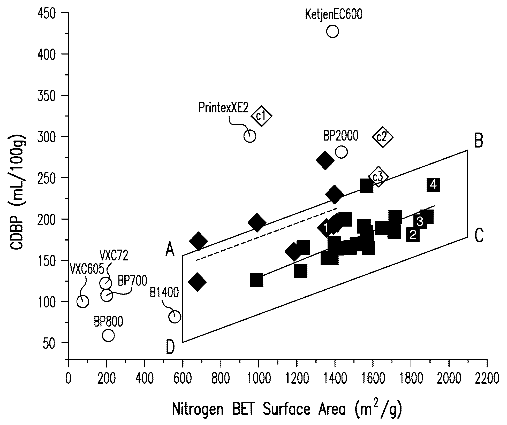
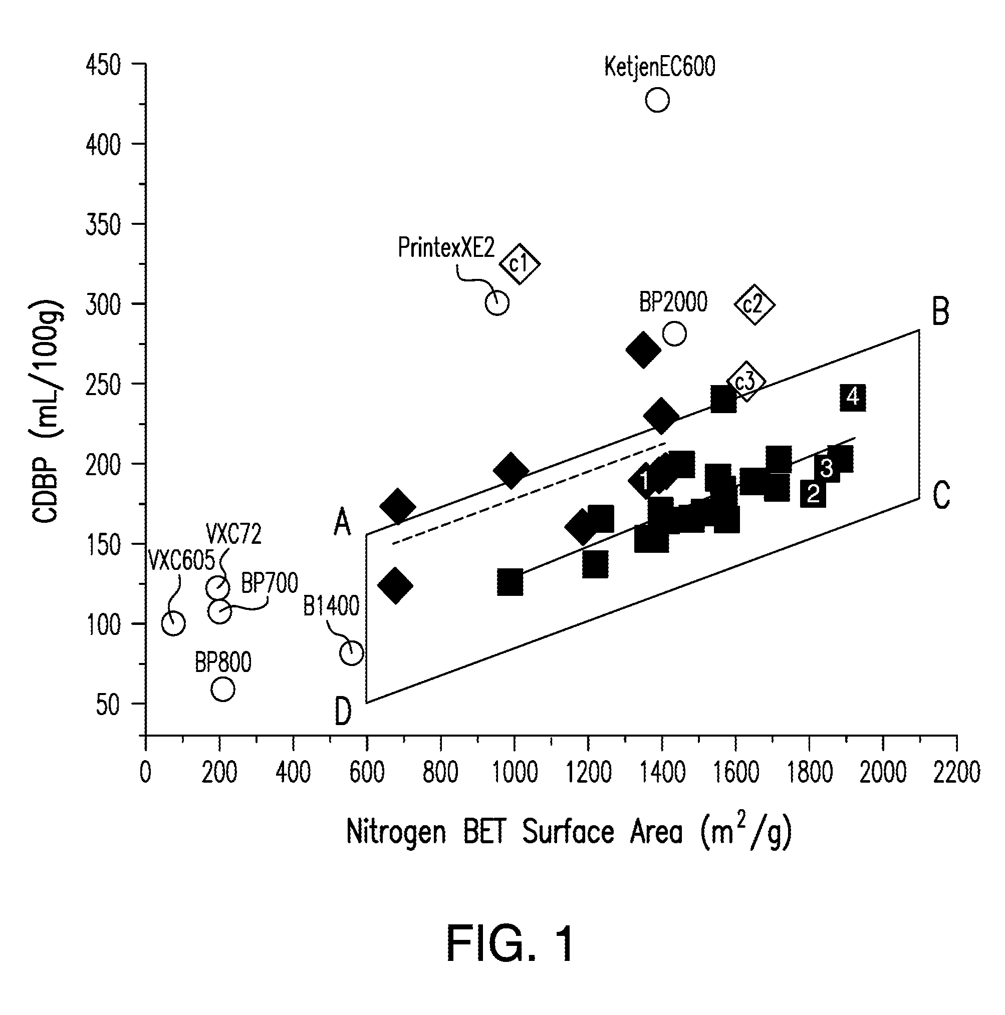
[0180]The four examples of carbon black (CB) 1-4 disclosed in Example 1 were analyzed for surface area, structure, and EDLC performance. With respect to surface area and structure, reference is made to carbon blacks 1-4 as identified by the corresponding number in solid square symbols in parallelogram ABCD in FIG. 1.

[0181]For each of the four examples of carbon black (CB) products, a dispersion of dry carbon black powder and polytetrafluoroethylene (PTFE) (available as 60 wt % solution from Aldrich) in water was prepared. The solid content of dispersion did not exceed 10 wt %. After homogenization, the mixture was dried at 85° C. over 48 hours to dry the water out so that the moisture content of the remaining carbon black / PTFE did not exceed 2 wt %. After grinding the resultant carbon black / PTFE composite with a commercial blender, the dry carbon black powder containing 12 wt % PTFE was rolled into a 145±10 micron thick electrode by a stainless steel...

example 3

[0188]The surface area, structure, and EDLC performance of one of the present invention's carbon black of Example 1 (Carbon Black 1) were determined and compared with those of carbon blacks made according to methods disclosed in U.S. Patent Application Publication No. 2009 / 0208751 A1 (c1, c2, and c3 as shown in FIG. 1). The EDLC sample preparation and performance measurement procedures used were similar to those in Example 2. The results are set forth in Table 4. As shown in the results in Table 4, Carbon Black 1 had superior overall characteristics and performance with respect to surface area, structure, and EDLC performance as compared to the comparative materials.

[0189]

TABLE 4electrodecellcellN2 BETpackinggravimetricvolumetricsurfaceCDBPDBPdensitycapacitancecapacitanceMaterialsarea (m2 / g)(mL / 100 g)(mL / 100 g)(g / cm3)@2 V (F / g)@2 V (F / cm3)carbon black 113581891950.5824.514.21c110103224000.318.85.6c21642296370c316272502780.4121.99


PUM

PropertyMeasurementUnit
average primary particle sizeaaaaaaaaaa
particle sizeaaaaaaaaaa
average primary particle sizeaaaaaaaaaa

Abstract

The present invention, in part, relates to a carbon black having a) a nitrogen BET surface area (BET) of from about 600 m2 / g to about 2100 m2 / g, b) a CDBP value in mL / 100 g of from about (−2.8+(b*BET)) to about (108+(b*BET)), where b is 0.087 and BET is expressed in m2 / g, and c) an apparent density (p, g / cm3) of at least about 0.820+q*BET, where q=−2.5×10⁻⁴, as determined at a compressive force (P) of 200 kgf / cm2 on dry carbon black powder. Energy storage devices, such as electrochemical double layer capacitors (EDLC's), containing the carbon black are also disclosed. Methods for making the carbon blacks and EDLC's made with them are also provided.

Description

[0001]This application claims the benefit under 35 U.S.C. §119(e) of prior U.S. Provisional Patent Application No. 61 / 257,226, filed Nov. 2, 2009, which is incorporated in its entirety by reference herein.[0002]The present invention relates to carbon blacks, and, particularly, high surface area, low structure carbon blacks. The present invention additionally relates to energy storage devices that use these carbon blacks. More particularly, the present carbon black can be used in an Electrochemical Double Layer Capacitor (EDLC), also known as an electrochemical capacitor, supercapacitor, or ultracapacitor. The EDLC can be a symmetric EDLC or other EDLC configurations. The application of the described carbon black is not restricted to the EDLC, but also may include other areas, including but not restricted to, the areas in the energy market such as batteries and fuel cells. Moreover, other devices that utilize the phenomenon of pseudocapacitance or utilize a hybrid design of a battery...

Claims


Application Information

Patent Timeline
Patent Type & Authority Patents(United States)
IPC IPC(8): H01G11/42H01M4/62H01G9/042H01G11/24H01M4/1393H01G11/38H01G11/32C09C1/58H01M8/10C09C1/48H01M4/133H01M4/583C09C1/56
CPCH01M4/133C01P2002/86C01P2004/62H01M4/1393C01P2004/64C01P2006/12Y02E60/13H01G11/24H01M4/583C09C1/48H01G11/32H01M4/625H01M8/1002H01G11/42H01G11/38C09C1/56H01G11/04H01M4/14H01M4/8673H01M10/06H01M12/005H01M2220/20H01M2250/20Y10T428/2982H01M8/1007Y02E60/10Y02E60/50H01G11/86Y02T90/40
Inventor KYRLIDIS, AGATHAGELOSSAWKA, RAYMOND M.MOESER, GEOFFREY D.KOSSYREV, PAVEL A.HARDMAN, NED J.
Owner CABOT CORP
Why Eureka
Try Eureka