Deacidification process and apparatus thereof

a deacidification process and apparatus technology, applied in separation processes, lighting and heating apparatus, furnaces, etc., can solve the problems of high energy consumption during deacidification, strong acidity of powder materials, and inability to overcome traditional technology defects by itself, so as to increase the resistance of the system, affect the stability of the product quality, and large fluctuation of the system pressure

Active Publication Date: 2016-03-01
GUANGZHOU GBS HIGH TECH & IND
View PDF14 Cites 0 Cited by
  • Summary
  • Abstract
  • Description
  • Claims
  • Application Information

AI Technical Summary

Benefits of technology

[0006]A principal object of the present invention is to provide a deacidification apparatus with low-energy and high efficiency.
[0022]1. In traditional deacidification technologies, a filtration apparatus such as bag-type dust remover is usually added in the exhaust outlet in to prevent powder from loss, but it likely to cause blocking to the filter and increase resistance to the system, to bring a large fluctuation to the system pressure, which affect the stability of the product quality. The present invention relates to a high temperature and high acid environment, but the traditional bag-type dust remover does not survive high temperatures so it is more likely to cause bag melting to affect the service life. The present invention uses negative pressure to remove the acid gas adsorbing at the surface of the powder material by the ceramic filter and filters the powder material effectively to overcome the defect that the powder material is easy to be discharged with the exhaust in the traditional fluidized bed deacidification apparatus causing the yield of the product decreased. The ceramic filter used in the present invention has the properties of high temperature resistance and resistance to chemical corrosion. Another important character of the present invention is that a pulsed gas is applied to the filter every 5˜300 seconds for reversing and flapping during the suction filtration to blow the powder material adsorbing at the surface of the filter down inside the deacidification apparatus to keep the system smooth, so as to ensure the stability of the product quality.
[0023]2. The deacidification apparatus is covered by an efficient heat insulation material which is a porous material made of a porous superfine powder, a glass fiber, a binding material and a heat radiation cover agent. The thermal conductivity of the heat insulation material is 0.03˜0.09 W / (m·K) at 500 degrees Celsius. When the deacidification apparatus is covered by such layer of insulation material with a thickness of 20-100 mm, even the temperature inside the deacidification apparatus is above 500 degrees Celsius, the temperature outside the deacidification apparatus can remains below 50 degrees Celsius, so the present invention can prevent heat loss, reduce energy consumption, consume 50 percent less energy than traditional means, and make the temperature inside the deacidification furnace less than that required in the traditional process, while a same or even better deacidification effect can be got.
[0024]3. The deacidification process of the present invention can effectively reduce the effective height (length) of the deacidification apparatus. In the traditional process, in order to effectively remove the acid gas adsorbing at the surface of the oxide powder material, the deacidification must be guaranteed to last a long time, so it needs to increase the height of the deacidification apparatus to extend the time of the powder material staying in the furnace, and sometimes even level 2 or 3 deacidification is needed. Another approach to achieve good deacidification effects in the traditional process is to increase the temperature inside the deacidification furnace. Because of the suction filtration used in the present invention which can remove the acid gas adsorbing at the surface of the oxide powder material effectively even at low temperatures, and the efficient heat insulation material used in the deacidification furnace, the effective height of the deacidification apparatus can be reduced, the investment cost can be saved, and the temperature inside the furnace can be lowered to reduce energy consumption.

Problems solved by technology

This gas makes the oxide powder material have strong acidity by adsorbing at its surface and affects its application.
The traditional technology has defects which cannot be overcome by itself.
Firstly, the deacidification requires a high temperature that the temperature should remain in 400˜750° C. inside the furnace, which leads to great energy consumption during deacidification.
Secondly, the powder material is easy to be discharged with the deacidification medium, so it needs to provide a filter such as bag-type dust remover in the exhaust outlet of the deacidification furnace, but the filter is likely to bring blocking, which causes the pressure of the system to destabilize.
Further, the deacidification in traditional technology is inefficient, in order to assure that the acid gas adsorbing at the surface of the powder material can be effectively removed, the height (length) of the deacidification furnace is relatively large to ensure the powder material can stay in the furnace long enough, and sometimes even the second or third deacidification is needed to ensure the PH value of the suspension 4 wt % aqueous solution of the deacidified product is larger than 3.6.
For a powder material prepared from pyrolysis, the water content is at a low level during production of the powder material, and the powder material forms a branch structure of spherical particles held together loosely, such that the loose structure tends to be collapsed after it is processed at high temperature in high water content, resulted in the collapse of the structure that it is easy to lose the specific features of the superfine powder from pyrolysis such as thickening, thixotropy, extinction and so on.
Moreover, the processing efficiency of the microwave heating per apparatus time is relatively low, so it is not good for mass powder deacidification.

Method used


Image

  • Deacidification process and apparatus thereof
  • Deacidification process and apparatus thereof

Examples


example one

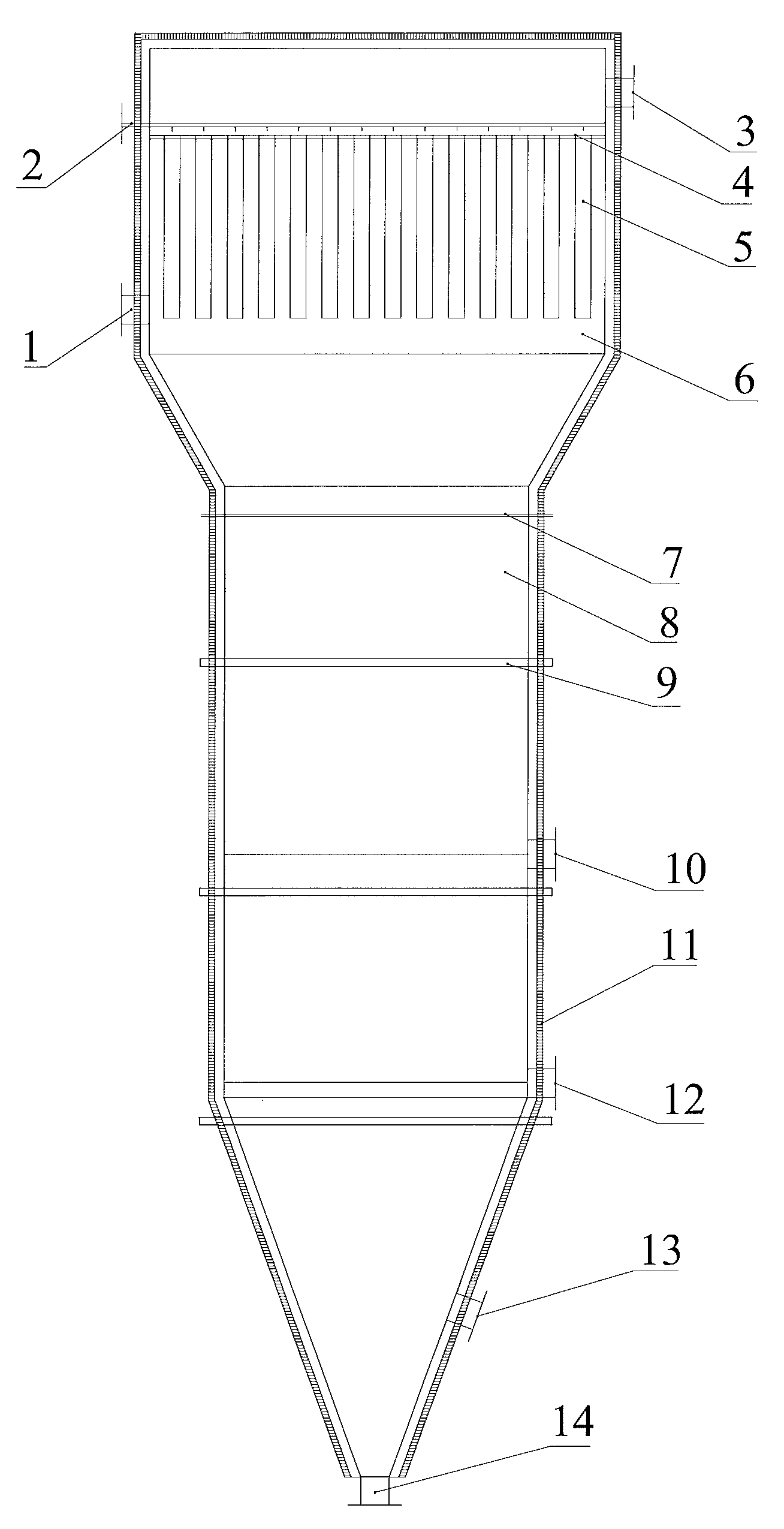
[0029]FIG. 1 is a schematic diagram illustrating a deacidification apparatus according to one embodiment of the present invention.

[0030]The deacidification apparatus includes a deacidification furnace, of which a furnace upper section, a furnace middle section and a furnace lower section are provided in upper, middle and lower portions respectively. The furnace upper section, the furnace middle section and the furnace lower section are connected by a flange 7. The furnace middle section is cylindrical, the furnace lower section forms a cone with a decreasing diameter downward, and the diameter of the furnace upper section is larger than that of the furnace middle section. A gas-solid mixture inlet 1, a exhaust outlet 3 and a filtered air port 2 are provided on the furnace upper section, a product outlet 13 is provided on the furnace lower section, and a filter plate 4 is provided on the furnace upper section, by which the filter 5 is mounted on the furnace upper section (filter barr...

example two

[0032]A deacidification process in accordance with the embodiment includes:

[0033]delivering a gas-solid mixture containing powders into the filter 5 by the gas-solid mixture inlet of the deacidification apparatus of Example One, carrying out suction filtration under vacuum, and discharging the acid gas on the surface of the mixture through the exhaust outlet 3 of the above deacidification apparatus, where the ceramic cartridge used in the deacidification apparatus has an aperture of 5 um, the porosity is 85%, and the total filter area is 72 m2, and where a pulsed gas is applied to the filter every 200 seconds for reversing and flapping during the suction filtration with a pressure of −6000 Pa to remove the powder material adsorbing at the surface of the filter; and driving the filtered powder into the furnace middle section of the deacidification furnace of the above deacidification apparatus, carrying out high temperature deacidification by heating from the assisted heating system ...

example three

[0036]The deacidification apparatus and the deacidification process using it of the embodiment are similar to those of Example Two, and the differences are as follows. In the embodiment, the ceramic cartridge used in the deacidification apparatus has an aperture of 10 um, the porosity is 95%, the total filter area is 72 m2, a pulsed gas is applied to the filter every 600 seconds for reversing and flapping during the suction filtration with a pressure of −4000 Pa, the temperature of the superheated vapor is 180 degrees Celsius, the high temperature air is a nitrogen gas with the temperature of 300 degrees Celsius, and the flow of the fumed silica is 220 kg / h.

[0037]The efficient heat insulation material is pressed for shaping from a fumed silica accounting for 50%, a glass fiber accounting for 15%, a sodium silicate accounting for 5% and a titanium dioxide accounting for 30% after mixed evenly, and the thickness of the heat insulation material for coating is 50 mm.

[0038]The PH value o...


PUM

PropertyMeasurementUnit
porosityaaaaaaaaaa
thicknessaaaaaaaaaa
pressureaaaaaaaaaa

Abstract

A deacidification apparatus and a deacidification process using the apparatus are disclosed. The deacidification apparatus includes a deacidification furnace, of which a furnace upper section, a furnace middle section and a furnace lower section are provided in upper, middle and lower portions respectively, wherein a gas-solid mixture inlet (1), a exhaust outlet (3) and a filtered air port (2) are provided on the furnace upper section, a product outlet (13) is provided on the furnace lower section, the upper portion of the deacidification is mounted with a filter (5) to which the gas-solid mixture inlet (1), the exhaust outlet (2) and the filtered air port (3) are connected, the filtered air port (2) is connected with a gas pulse device and a vacuum device by a three-way connecting device, and the exhaust outlet (3) is connected with atmosphere or connected with the vacuum device.

Description

TECHNICAL FIELD[0001]The present invention relates to a deacidification apparatus and a deacidification process using the apparatus.BACKGROUND[0002]A pyrogenic oxide is an oxide powder material prepared from the hydrolysis-polycondensation of halide such as silicon tetrachloride, methyl trichlorosilane, titanium tetrachloride and aluminium chloride, used as a raw material at high temperatures. The principle of the hydrolysis-polycondensation is as follows:MClx+H2+O2→M2OxHCl.[0003]It can be known from the above reaction equation that a hydrogen chloride gas is generated during the course of reaction. This gas makes the oxide powder material have strong acidity by adsorbing at its surface and affects its application. Thus it generally needs to remove the acid gas absorbed at the surface of the oxide powder material by deacidifying during the production.[0004]The existing deacidification technology uses a high temperature desorption with assisted deacidification medium way for deacidif...

Claims


Application Information

Patent Timeline
Patent Type & Authority Patents(United States)
IPC IPC(8): B01D53/40B01D46/00B01D53/68C01B33/12F23J15/02C01B33/18B01J19/00F27D17/00F27D1/00
CPCF23J15/02B01J19/00F27D1/0033F27D17/001B01D53/40B01D53/685F23J2217/101B01D2257/2045B01D46/0068C01B33/12C01B33/18B01D46/71
Inventor WU, CHUNLEIDUAN, XIANJIANLONG, CHENGKUNWANG, YUELIN
Owner GUANGZHOU GBS HIGH TECH & IND
Why Eureka
Try Eureka