Lithium-sulfur secondary battery containing gradient electrolyte

a lithium-sulfur battery and gradient electrolyte technology, which is applied in the direction of cell components, electrochemical generators, transportation and packaging, etc., can solve the problems of further commercialization, short circuit and explosion of internal short circuit of these types of secondary batteries, and achieve low electric and ionic conductivity, prevent potential li metal dendrite-induced internal short circuit and thermal runaway problems of li metal-sulfur batteries

Active Publication Date: 2018-01-30
GLOBAL GRAPHENE GRP INC
View PDF6 Cites 6 Cited by
  • Summary
  • Abstract
  • Description
  • Claims
  • Application Information

AI Technical Summary

Benefits of technology

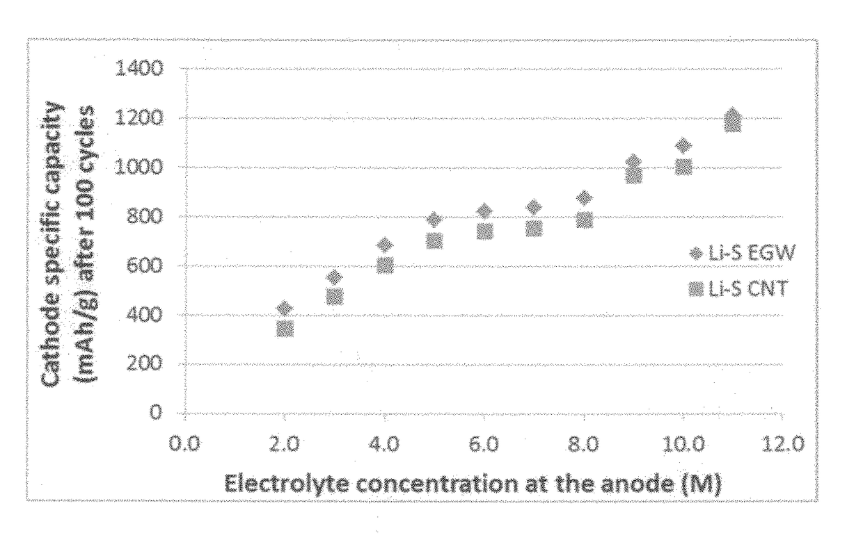
[0060](1) The lithium-sulfur cell featuring a gradient electrolyte system exhibits a stable and safe anode (no dendrite-like feature), high lithium utilization rate, high cathode active material utilization rate, high specific capacity, high specific energy, high power density, little or no shuttling effect, and long cycle life.
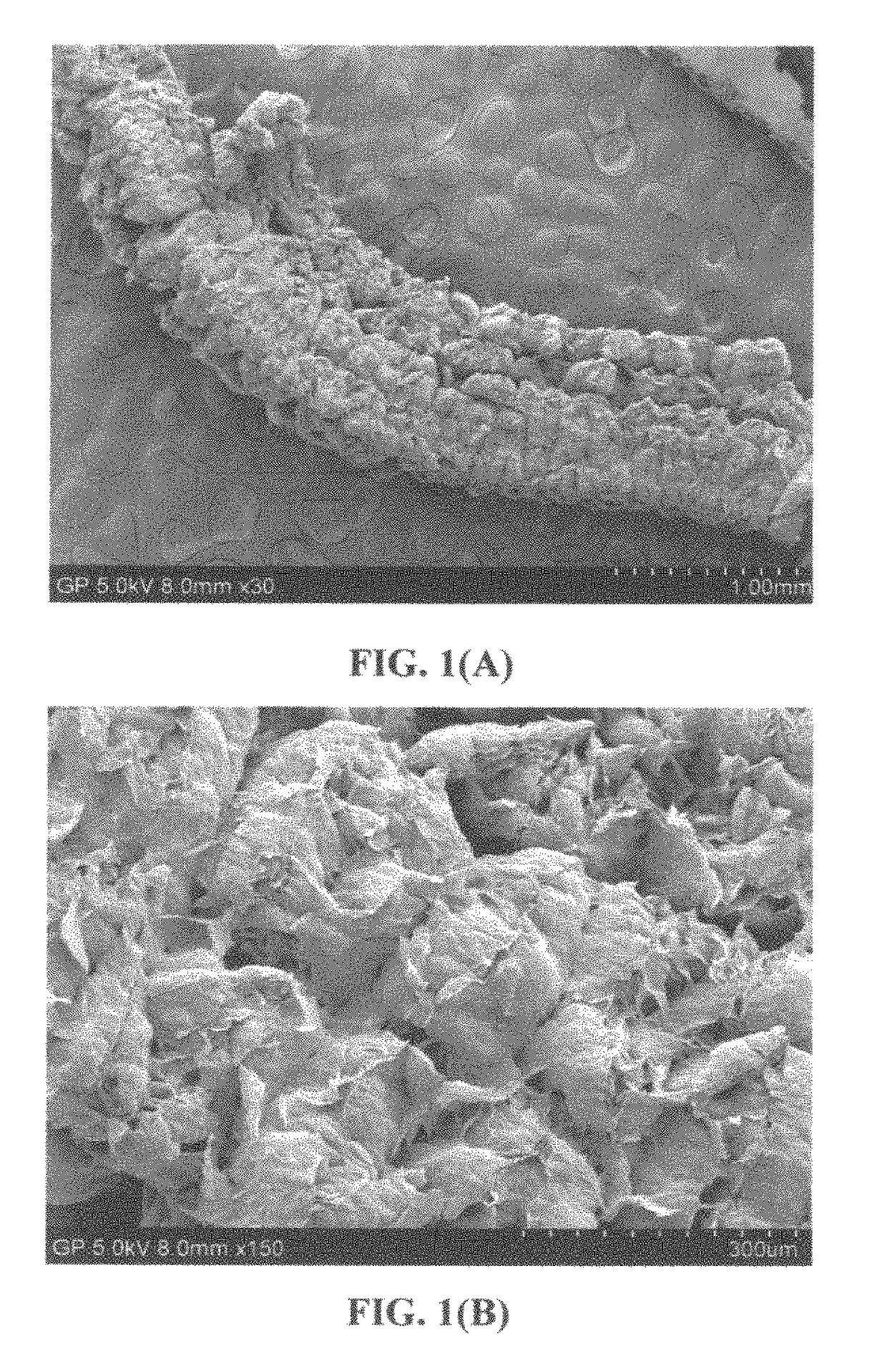
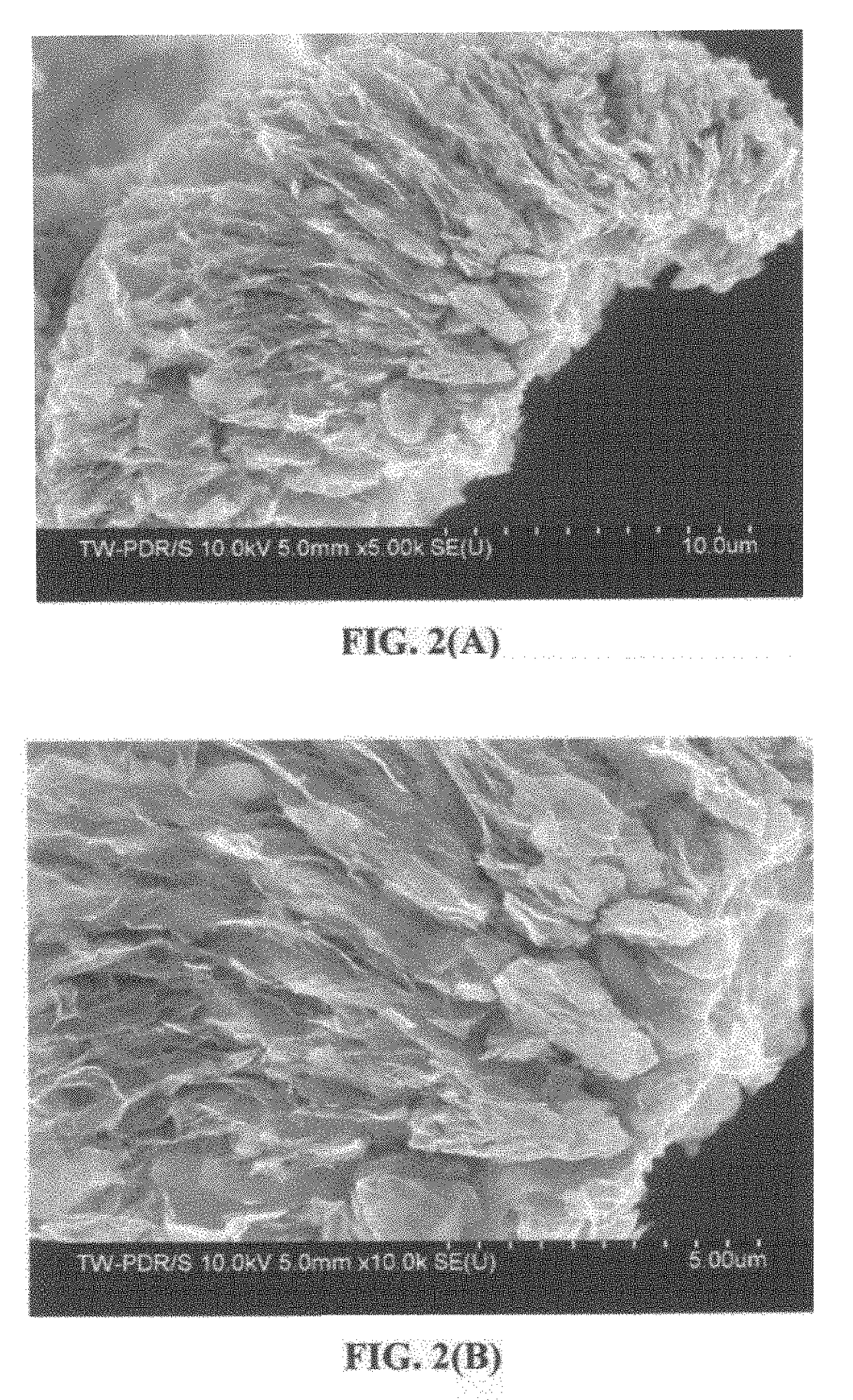
[0061](2) The approach of using a gradient electrolyte system may be coupled with the strategy of using a meso-porous exfoliated graphite worm structure to support sulfur and / or lithium polysulfide at the cathode. This combination has essentially eliminated the shuttling effect and provides other additional benefits. The meso-scaled pores of the graphite worm network are capable of retaining sulfur and lithium polysulfide in the pores, only allowing lithium ions (not lithium polysulfide species) to move out of the pores. Surprisingly, these graphite worm-based meso-porous structures were very effective in addressing the shuttle effect issues. Further, the interconnected network of graphite flakes forms a continuous path for electrons, resulting in significantly reduced internal energy loss or internal heating. The meso-pores also imply the lithium polysulfide or sulfur component inside the pores being nanometer-sized, enabling a fast cathode reaction. Hence, the cell is capable of being re-charged at a high rate. This is a highly beneficial feature for a battery that is intended for high power applications such as electric vehicles.
[0064]a. In one situation, the anode is initially lithium metal-free (when the cell is made) and lithium is stored as part of lithium polysulfide at the cathode. During the first charging operation of a Li-metal cell featuring a meso-porous exfoliated graphite worm cathode and a nano-structured anode, lithium ions move from the cathode to the anode and deposit onto the surfaces of nano-filaments to form a lithium metal coating. Surprisingly, as an added feature, the nano-structure at the anode provides an environment that is conducive to uniform deposition of lithium atoms, to the extent that no geometrically sharp structures or dendrites were found in the anode after a large number of cycles. The 3-D network of highly conductive filaments appears to be capable of providing substantially uniform electric fields and, hence, uniform attraction of lithium ions back onto the filament surfaces during re-charging. The higher electrolyte concentration at the anode side also promotes a more uniform lithium deposition during re-charging operations. These combined features appear to have totally eliminated the dendrite formation issue. During the subsequent discharge operation, the nano-structured anode with thin, nano-scaled lithium coating is capable of quickly releasing lithium and thus capable of being discharged at a high rate.
[0065]b. In another situation, the anode contains a nano-structure of conductive filaments (e.g. CNTs or graphene sheets) that is pre-lithiated or is in contact with a lithium foil when the cell is made. The cathode has a meso-porous exfoliated graphite worm structure to accommodate thin sulfur coating. During the first discharge, lithium ions are released from conductive filament surfaces or lithium foil, migrating to the cathode side, and react with sulfur to form lithium polysulfide or lithium sulfide. Since the sulfur coating is very thin, lithium ions are capable of reaching most of the available sulfur, achieving a high sulfur utilization rate. The presence of a low-concentration electrolyte at the cathode is particularly amenable to facile lithium ion transport in the cathode, making it possible to reach sulfur even under a relatively high current or high power condition. (The presence of a higher concentration electrolyte next to this lower concentration electrolyte serves to prevent or reduce the dissolved lithium polysulfide species from transporting to the anode side.)

Problems solved by technology

Unfortunately, upon cycling, the lithium metal resulted in the formation of dendrites at the anode that ultimately caused internal shorting and explosion.
As a result of a series of accidents associated with this problem, the production of these types of secondary batteries was stopped in the early 1990's giving ways to lithium-ion batteries.
Even now, cycling stability and safety concerns remain the primary factors preventing the further commercialization of Li metal batteries for EV, HEV, and microelectronic device applications.
Again, cycling stability and safety issues of lithium metal rechargeable batteries are primarily related to the high tendency for Li metal to form dendrite structures during repeated charge-discharge cycles or overcharges, leading to internal electrical shorting and thermal runaway.
However, despite these earlier efforts, no rechargeable Li metal batteries have succeeded in the market place.
This is likely due to the notion that these prior art approaches still have major deficiencies.
For instance, in several cases, the anode or electrolyte structures are too complex.
In others, the materials are too costly or the processes for making these materials are too laborious or difficult.
Although lithium-ion (Li-ion) batteries are promising energy storage devices for electric drive vehicles, state-of-the-art Li-ion batteries have yet to meet the cost and performance targets.
In summary, despite its considerable advantages, the Li—S cell is plagued with several major technical problems that have hindered its widespread commercialization:(1) Conventional lithium metal cells still have dendrite formation and related internal shorting issues;(2) Sulfur or sulfur-containing organic compounds are highly insulating, both electrically and ionically.
Various carbon-sulfur composites have been utilized for this purpose, but only with limited success owing to the scale of the contact area.
This is mainly due to the high solubility of the lithium polysulfide anions formed as reaction intermediates during both discharge and charge processes in the polar organic solvents used in electrolytes.
In addition, the solid product that precipitates on the surface of the positive electrode during discharge becomes electrochemically irreversible, which also contributes to active mass loss.(4) More generally speaking, a significant drawback with cells containing cathodes comprising elemental sulfur, organosulfur and carbon-sulfur materials relates to the dissolution and excessive out-diffusion of soluble sulfides, polysulfides, organo-sulfides, carbon-sulfides and / or carbon-polysulfides (hereinafter referred to as anionic reduction products) from the cathode into the rest of the cell.
This process leads to several problems: high self-discharge rates, loss of cathode capacity, corrosion of current collectors and electrical leads leading to loss of electrical contact to active cell components, fouling of the anode surface giving rise to malfunction of the anode, and clogging of the pores in the cell membrane separator which leads to loss of ion transport and large increases in internal resistance in the cell.
Some interesting cathode developments have been reported recently to contain lithium polysulfides; but, their performance still fall short of what is required for practical applications.
However, the fabrication of the proposed highly ordered meso-porous carbon structure requires a tedious and expensive template-assisted process.
Most significantly, lithium metal (including pure lithium, alloys of lithium with other metal elements, or lithium-containing compounds) still provides the highest anode specific capacity as compared to essentially all other anode active materials (except pure silicon, but silicon has pulverization issues).
It may be noted that in most of the open literature reports (scientific papers), scientists choose to express the cathode specific capacity based on the sulfur or lithium polysulfide weight alone (not total cathode composite weight), but unfortunately a large proportion of non-active materials (those not capable of storing lithium, such as conductive additive and binder) is typically used in their Li—S cells.

Method used


Image

  • Lithium-sulfur secondary battery containing gradient electrolyte
  • Lithium-sulfur secondary battery containing gradient electrolyte
  • Lithium-sulfur secondary battery containing gradient electrolyte

Examples


example 1

Exfoliated Graphite Worms from Natural Graphite

[0167]Natural graphite, nominally sized at 45 μm, provided by Asbury Carbons (405 Old Main St., Asbury, N.J. 08802, USA) was milled to reduce the size to approximately 14 μm. The chemicals used in the present study, including fuming nitric acid (>90%), sulfuric acid (95-98%), potassium chlorate (98%), and hydrochloric acid (37%), were purchased from Sigma-Aldrich and used as received.

[0168]A reaction flask containing a magnetic stir bar was charged with sulfuric acid (360 mL) and nitric acid (180 mL) and cooled by immersion in an ice bath. The acid mixture was stirred and allowed to cool for 15 min, and graphite (20 g) was added under vigorous stirring to avoid agglomeration. After the graphite powder was well dispersed, potassium chlorate (110 g) was added slowly over 15 min to avoid sudden increases in temperature. The reaction flask was loosely capped to allow evolution of gas from the reaction mixture, which was stirred for 48 hours...

example 2

Exfoliated Graphite Worms from Various Synthetic Graphite Particles or Fibers

[0169]Additional exfoliated graphite worms were prepared according to the same procedure described in Example 1, but the starting graphite materials were graphite fiber (Amoco P-100 graphitized carbon fiber), graphitic carbon nano-fiber (Pyrograph-III from Applied Science, Inc., Cedarville, Ohio), spheroidal graphite (HuaDong Graphite, QinDao, China), and meso-carbon micro-beads (MCMBs) (China Steel Chemical Co., Taiwan), respectively. These four types of laminar graphite materials were intercalated and exfoliated under similar conditions as used for Example 1 for different periods of time, from 24 hours to 96 hours.

example 3

Exfoliated Graphite Worms from Natural Graphite Using Hummers Method

[0170]Additional graphite intercalation compound (GIC) was prepared by intercalation and oxidation of natural graphite flakes (original size of 200 mesh, from Huadong Graphite Co., Pingdu, China, milled to approximately 15 μm) with sulfuric acid, sodium nitrate, and potassium permanganate according to the method of Hummers [U.S. Pat. No. 2,798,878, Jul. 9, 1957]. In this example, for every 1 gram of graphite, we used a mixture of 22 ml of concentrated sulfuric acid, 2.8 grams of potassium permanganate, and 0.5 grams of sodium nitrate. The graphite flakes were immersed in the mixture solution and the reaction time was approximately three hours at 30° C. It is important to caution that potassium permanganate should be gradually added to sulfuric acid in a well-controlled manner to avoid overheat and other safety issues. Upon completion of the reaction, the mixture was poured into deionized water and filtered. The samp...


PUM

PropertyMeasurementUnit
melting pointaaaaaaaaaa
sizeaaaaaaaaaa
sizeaaaaaaaaaa

Abstract

A rechargeable lithium-sulfur cell comprising a cathode, an anode, a separator electronically separating the two electrodes, a first electrolyte in contact with the cathode, and a second electrolyte in contact with the anode, wherein the first electrolyte contains a first concentration, C1, of a first lithium salt dissolved in a first solvent when the first electrolyte is brought in contact with the cathode, and the second electrolyte contains a second concentration, C2, of a second lithium salt dissolved in a second solvent when the second electrolyte is brought in contact with the anode, wherein C1 is less than C2. The cell exhibits an exceptionally high specific energy and a long cycle life.

Description

FIELD OF THE INVENTION[0001]The present invention provides a unique electrolyte composition in a secondary or rechargeable lithium-sulfur battery, including the lithium metal-sulfur battery and the lithium ion-sulfur battery.BACKGROUND[0002]Rechargeable lithium-ion (Li-ion), lithium metal, and Li metal-air batteries are considered promising power sources for electric vehicle (EV), hybrid electric vehicle (HEV), and portable electronic devices, such as lap-top computers and mobile phones. Lithium as a metal element has the highest capacity (3,861 mAh / g) compared to any other metal or metal-intercalated compound as an anode active material (except Li4.4Si, which has a specific capacity of 4,200 mAh / g). Hence, in general, Li metal batteries have a significantly higher energy density than lithium ion batteries.[0003]Historically, rechargeable lithium metal batteries were produced using non-lithiated compounds relatively having high specific capacities, such as TiS2, MoS2, MnO2, CoO2, an...

Claims


Application Information

Patent Timeline
Patent Type & Authority Patents(United States)
IPC IPC(8): H01M4/36H01M4/136H01M4/38H01M4/58H01M10/052H01M10/056H01M4/66H01M10/0566H01M4/80H01M4/134H01M4/74
CPCH01M10/056H01M4/38H01M4/382H01M4/5815H01M4/663H01M4/80H01M4/806H01M10/052H01M10/0566H01M4/136Y02T10/7011H01M4/134H01M4/668H01M4/747H01M2300/0025Y02E60/122Y02E60/10Y02T10/70
Inventor HE, HUIJANG, BOR ZWANG, YANBOZHAMU, ARUNAXIONG, WEI
Owner GLOBAL GRAPHENE GRP INC
Why Eureka
Try Eureka