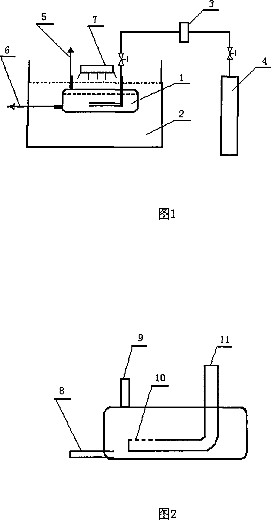
Three-phase ultrasound light-catalyzed reaction device and method for CO2 reduction thereof
A photocatalytic reaction, CO2 technology, applied in chemical instruments and methods, separation methods, chemical/physical processes, etc., can solve the problems of low effective utilization of light, high toxicity of organic solvents, low reduction efficiency, etc., to achieve improved reduction effect, shortened reaction time, effect of shortened light time
- Summary
- Abstract
- Description
- Claims
- Application Information
AI Technical Summary
Problems solved by technology
Method used
Image
Examples
Embodiment 1
[0026] Catalyst prepared by in-situ synthesis method: Add butyl titanate, ethanol, and acetic acid into a three-necked flask with a stirrer at a ratio of 1:4:4, and then add phthalonitrile and metal salt solution to the butyl titanate phase Add in a ratio of 0.7%, add a certain amount of solvent and keep stirring, adjust the pH to about 4 with hydrochloric acid, react for 14 hours, place and age for 24 hours, dry at 100°C, roast and grind at 400°C, and prepare granular in-situ synthesized CoPc / TiO 2 catalyst of light. According to XRD analysis, it can be known that TiO 2 The crystal form is mainly anatase type, and the average diameter of the catalyst is 15nm. 2 CoPc was synthesized in situ on the surface.
[0027] CO of the present invention 2 The reduction process flow is as follows: 150 mg of the prepared photocatalyst and 100 mL of 0.1 mol / L sodium hydroxide solution are placed in a quartz tube photoreactor, and then the photoreactor is placed in the water bath of the ...
Embodiment 2
[0032] In the photoreactor made of Pyrex glass tube, 200 mg of photocatalyst and 100 mL of 0.1 mol / L sodium hydroxide solution in Example 1 were added, and CO 2 After a certain period of time, the gas inlet is closed. The light source is sunlight gathered by a concave mirror. The distance between the light source and the photoreactor is 80cm. Then the photoreactor is placed in the water bath of the ultrasonic generator. The ultrasonic power is 200W and the frequency 50KHz, after 18 hours of irradiation and ultrasonic reaction, the product can be analyzed to obtain 307.9 μmol / g-cat of formic acid, 261.8 μmol / g-cat of formaldehyde, and 53.6 μmol / g-cat of methanol.
Embodiment 3
[0037] Preparation of photocatalyst by impregnation method: Commercial TiO produced by Beijing Chemical Plant 2 After activation at a constant temperature of 500°C for 2 hours, place in the organic solvent toluene, dissolve cobalt phthalocyanine (CoPc), press TiO 2 The mass ratio of CoPc to CoPc was added at a ratio of 100:3, and after impregnation for a certain period of time, the CoPc / TiO prepared by impregnation method was obtained. 2 Catalyst, dried and calcined at 250°C, XRD analysis shows that TiO 2 The crystal form is mainly anatase type, and the average diameter of the catalyst is 58nm. CO 2 The reduction process flow is as in Example 1, the CoPc / TiO prepared by the impregnation method 2 Catalyst 150mg and 0.1mol / L 100mL sodium hydroxide aqueous solution are placed in a quartz tube photoreactor, then the photoreactor is placed in an ultrasonic generator, and CO is introduced into the photoreactor 2 After the gas is ventilated, under ultrasonic stirring, visible lig...
PUM
 Abstract
Description
Claims
Application Information
 - R&D
- Intellectual Property
- Life Sciences
- Materials
- Tech Scout
- Unparalleled Data Quality
- Higher Quality Content
- 60% Fewer Hallucinations
Browse by: Latest US Patents, China's latest patents, Technical Efficacy Thesaurus, Application Domain, Technology Topic, Popular Technical Reports.
© 2025 PatSnap. All rights reserved.Legal|Privacy policy|Modern Slavery Act Transparency Statement|Sitemap|About US| Contact US: help@patsnap.com

