Method of hydrolysis-catalytic iron-aerobic coupling for treating poisonous and harmful hard-degradation waste water

A catalytic iron, refractory technology, applied in water/sewage treatment, chemical instruments and methods, water/sewage multi-stage treatment, etc. and the effect of the impact of the water load

Inactive Publication Date: 2010-04-14
TONGJI UNIV +1
View PDF4 Cites 16 Cited by
  • Summary
  • Abstract
  • Description
  • Claims
  • Application Information

AI Technical Summary

Problems solved by technology

However, these methods require pretreatment such as sedimentation or air flotation when treating wastewater with high SS concentration, and because the catalytic iron filler and the organism are directly coupled in a pool, although the space is saved, the adjustment is not flexible during operation. Need to take steps to improve

Method used


Image

  • Method of hydrolysis-catalytic iron-aerobic coupling for treating poisonous and harmful hard-degradation waste water

Examples


Embodiment 1

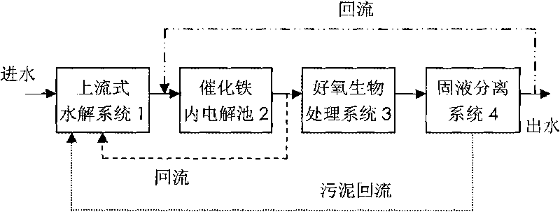
[0023] 1. The chemical industrial park wastewater that has been preliminarily treated by grille and sand settling enters the upstream hydrolysis system 1 directly, and the residence time in this system is 5.5h. The hydrolysis system adopts the biofilm type. The hydrolysis tank requires a good water distribution system and Mud discharge system.

[0024] 2. Catalytic iron inner electrolytic cell 2 The catalytic iron filler is composed of iron shavings and copper shavings, the mass ratio of the two is 20:1, and the bulk specific gravity is 0.2. The contact time of the filling area is 1.5h, and it is required to be completely submerged in water. The catalytic iron is required to be upflow type, and a good water distribution system and slag discharge system are required. The reflux ratio of the effluent of the catalytic iron inner electrolytic cell 2 to the upflow hydrolysis system 1 is 100%.

[0025] 3. The aerobic biological treatment system 3 uses suspended biological carriers...

Embodiment 2

[0029] 1. The printing and dyeing wastewater treated by the grid directly enters the upstream hydrolysis system 1, and the residence time in this system is 9.0h. The hydrolysis system adopts the suspended sludge type, and a good water distribution system and sludge discharge system are required in the hydrolysis tank.

[0030] 2. Catalytic iron inner electrolytic cell 2 The catalytic iron filler is composed of iron shavings and copper shavings, the mass ratio of the two is 10:1, and the bulk specific gravity is 0.3. The contact time of the filling area is 0.5h, and it is required to be completely submerged in water. The catalytic iron is required to be upflow type, and a good water distribution system and slag discharge system are required. The reflux ratio of the effluent from the catalytic iron inner electrolytic cell 2 to the upflow hydrolysis system 1 is 40%.

[0031] 3. Aerobic biological treatment system 3 adopts elastic packing carrier. For the fluid state, the plug-f...


PUM


Abstract

The invention pertains to the technical field of treatment of waste water, and particularly relates to a method of hydrolysis-catalytic iron-aerobic coupling for treating poisonous and harmful hard-degradation waste water, which comprises the following steps: waste water after primary treatment directly enters an up flow type hydrolysis system 1 and stays for 4.0-10.0 hours; the effluent enters an electrolytic cell in the catalytic iron; the mass ratio of iron scraps and copper scraps in the electrolytic cell of the catalytic iron is 1:1 to 20:1, the bulk specific weight thereof is 0.1 to 0.3, the contact time thereof in a filling area is 0.5 to 2.0 hours, and the reflux ratio of the effluent refluxing to the up flow type hydrolysis system is 20 to 100 percent; the effluent enters an aerobic biological treatment system and stays for 6.0 to 12.0 hours; then the effluent enters a solid-liquid separation system with a reflux ratio of sludge being 10 to 50 percent; and the effluent of the solid-liquid separation system refluxes to the electrolytic cell of the catalytic iron with the reflux ratio being 20 to 200 percent. Under the premise of fully playing the function of different treatment units and maintaining the treatment effect and respective advantages, the treatment method of waste water realizes the coupling synergetic action of the three units, strengthens the impact of the system to water quality and water quantity load, reduces a plurality of steps of pretreatment, effectively improves the removal rate of ammonia nitrogen, and can be flexibly adjusted.

Description

technical field [0001] The invention belongs to the technical field of wastewater treatment, and in particular relates to a hydrolysis-catalyzed iron-aerobic coupling method for treating toxic, harmful and refractory wastewater. Background technique [0002] In order to improve the treatment effect of toxic, harmful and refractory wastewater, scientific research and engineering personnel have developed a variety of related technologies and treatment processes, such as hydrolysis technology, catalytic reduction technology and a variety of advanced Oxidation technology, etc., these technologies are mainly used as pretreatment units; contact oxidation to increase microbial biomass and biological activity, biofilm technology such as fluidized bed, MBR technology, and engineering bacteria feeding technology, etc., these are usually used as the main core treatment process. According to the different treatment purposes of the above-mentioned different technologies and the character...

Claims


Application Information

Patent Timeline
Patent Type & Authority Applications(China)
IPC IPC(8): C02F9/14C02F1/461C02F3/12
CPCY02W10/10
Inventor 刘志刚胡坚王红武樊金红赵宝康吴德礼蒋波马鲁铭许立群
Owner TONGJI UNIV
Why Eureka
Try Eureka