
Low-reflection optical interface layer and preparation method thereof

An optical interface, low-reflection technology, applied in optics, optical components, coatings, etc., can solve the problems of reducing the film forming temperature, changing the refractive index of the polymer substrate, deformation, etc. Effect

Inactive Publication Date: 2010-07-07
SICHUAN UNIV
View PDF3 Cites 11 Cited by
  • Summary
  • Abstract
  • Description
  • Claims
  • Application Information

AI Technical Summary

Problems solved by technology

However, the low surface energy of polymers, deformation above the glass transition temperature, and much lower heat resistance than inorganic materials make it very difficult to fabricate AR interfaces on polymer optical materials.
Therefore, the traditional vacuum vapor deposition technology cannot be directly used to prepare anti-reflection coatings on polymer substrates, and methods such as plasma must be used to reduce the film-forming temperature.
But in doing so, the polymer substrate is exposed to high-energy ions or short-wave radiation, which breaks the polymer chain, generates free radicals, causes other reactions, changes the polymer chain structure, and thus changes the refractive index of the polymer substrate, affecting its optical properties
Other methods, such as physical and chemical methods such as thermal embossing, track etching or plasma etching, all have shortcomings such as time-consuming and labor-intensive manufacturing processes, and poor anti-reflection effects.

Method used


Image

  • Low-reflection optical interface layer and preparation method thereof
  • Low-reflection optical interface layer and preparation method thereof

Examples


Embodiment 1

[0034] Example 1 - Inorganic Substrate

[0035] The cleaning of the inorganic substrate is to first immerse the substrate in the washing solution prepared by concentrated sulfuric acid and hydrogen peroxide at a volume ratio of 3:1, then ultrasonically clean it with deionized water and ethanol in turn, and finally place it in a dry and clean container to dry for later use;

[0036] This embodiment is applicable to the cleaning of metal substrates, silicon wafer substrates, and inorganic oxide substrates such as glass and quartz.

Embodiment 2

[0037] Example 2 - Organic Substrate

[0038] The organic substrate was cleaned by ultrasonic cleaning three times with absolute ethanol, and then placed in a dry clean container to dry for later use.

[0039] This embodiment is applicable to the cleaning of polymethyl methacrylate (PMMA), polycarbonate (PC), polyester (PET), polystyrene (PSt) and other materials.

[0040] Examples of Nanoparticle Preparation

Embodiment 3

[0041] Embodiment 3-emulsion polymerization prepares organic nanoparticle-PMMA particle:

[0042] Add 300 g of deionized water and 0.6 g of emulsifier sodium lauryl sulfate in a 500 ml three-necked round bottom flask equipped with mechanical stirring, and start stirring to make the emulsifier completely dissolve in deionized water. Then add 60g of distilled and purified MMA monomer and pre-emulsify at about 23°C for about 30 minutes, then add 0.18g of potassium persulfate, pass nitrogen, slowly raise the temperature to about 70°C for about 5 hours, and then raise the temperature to about 80°C for about 30 minutes. 2 hours to complete the reaction. The resulting emulsion was filtered to obtain a PMMA emulsion with a particle size of about 60 nm and a distribution coefficient of 1.2.


PUM

PropertyMeasurementUnit
thicknessaaaaaaaaaa
sizeaaaaaaaaaa
sizeaaaaaaaaaa

Abstract

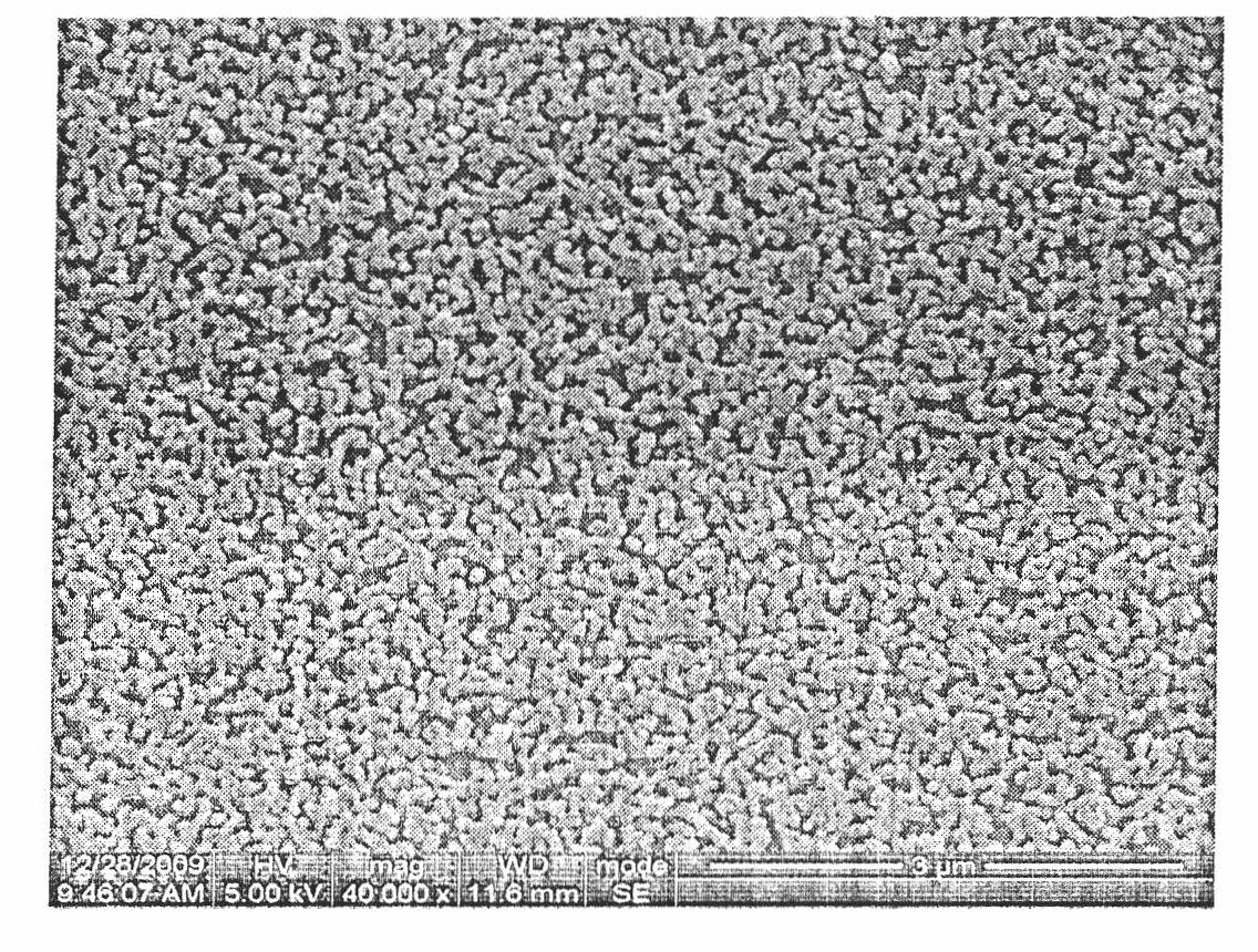
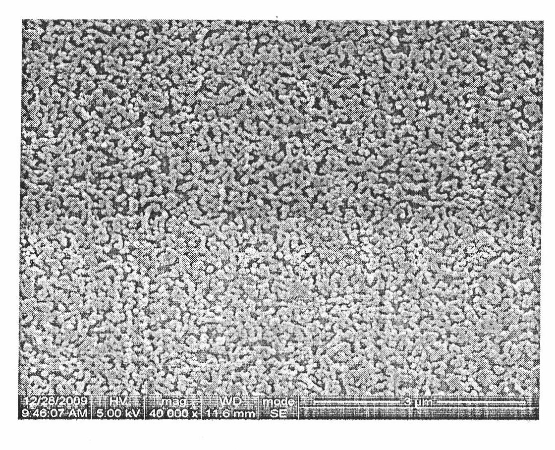
The invention discloses a low-reflection optical interface layer and a preparation method thereof. The interface layer is a nanometer porous particle film formed by nanometer particles deposited on a base material, the thickness of the film is 50-200nm, the sizes of the pores in the film are 50-200nm, and the porosity of the film is 30-75%. The preparation method comprises the following steps of: (1) preparing at least two nanometer particles into dispersion liquid with a mass concentration of 0.3-8.0%; (2) depositing the nanometer particle dispersion liquid on the base material to form a nanometer particle composite film; (3) selectively removing sacrificial components in the nanometer particle composite film; and (4) thermally treating an accessory for a certain time at a temperature approximate to the glass transition temperature of organic particles and the organic base material. The low-reflection optical interface layer provided by the invention has a reflectance less than 1% when incident electromagnetic waves are in the range of 360-900nm, and the reflectance at the lowest place is less than 0.5%. The low-reflection optical interface layer has high binding strength with the base material and stable optical performance. The optical interface layer is simple to process, and the optical interface layer with low reflectance is suitable to be prepared on organic and inorganic base materials with large areas.

Description

technical field [0001] The invention relates to the technical field of optical elements, and more specifically relates to a reflective optical interface layer on an optical element base material and a preparation method of the optical interface layer. Background technique [0002] Optical components, such as computer TV display screens, instrumentation display panels, optical lenses, high-power lasers, and the surfaces of display windows, solar panels, etc., all need to reduce reflected light, increase light transmittance, and improve the imaging quality of optical systems, or Obtain better photoelectric conversion efficiency. In addition, there are many occasions in daily life that need to reduce surface reflection. The anti-reflection principle of the optical interface is roughly: when light passes through the optical interface, the reflected light and transmitted light generated at the optical interface will interfere with light, and the refractive index and thickness of...

Claims


Application Information

Patent Timeline
Patent Type & Authority Applications(China)
IPC IPC(8): G02B1/11C08J9/26C08J7/04C03C17/25C03C17/28G02B1/111
Inventor 王跃川姜浩
Owner SICHUAN UNIV
Learn More