

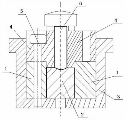
Method for manufacturing grid of millimeter-wave traveling wave tube
A traveling wave tube and millimeter wave technology, which is applied in the field of preparation of traveling wave tube parts, can solve the problems of many spokes, high probability of grid ignition, narrow bandwidth beam, etc. Actionable effect
- Summary
- Abstract
- Description
- Claims
- Application Information
AI Technical Summary
Problems solved by technology
Method used
Image

Examples
Embodiment 1
[0029] Example 1 Preparation of the grid of the millimeter wave traveling wave tube
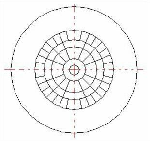
[0030](a) Design the size of the plane grid, select the grid molybdenum base material with a thickness of 0.06mm according to the plane grid size, remove the impurity particles on the surface of the grid molybdenum base material, and rotate it on the grid molybdenum base material surface (500 Rotation per minute at low speed, dripping glue, 3000 rpm accelerated rotation, glue rejection, volatile solvent) coating a novolac resin positive photoresist with a thickness of 1 μm, and then baking on a hot plate at 110°C for 30 seconds in a vacuum state , and then align the mask plate and the scattering grating pattern with the photoresist on the grid molybdenum substrate, and then use an optical lithography machine (high-pressure mercury lamp) for projection exposure treatment. The developer solution is applied to the surface of the substrate and forms a puddle shape to keep the flow of the develope...
Embodiment 2
[0034] Example 2 Preparation of the grid of the millimeter wave traveling wave tube
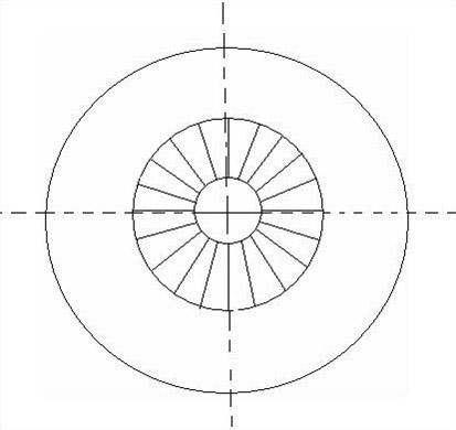
[0035] (a) Design the size of the plane grid, select the grid molybdenum-rhenium substrate with a thickness of 0.08mm according to the size of the plane grid, remove the impurity particles on the surface of the grid molybdenum-rhenium substrate, and rotate it on the surface of the grid molybdenum-rhenium substrate. Coating (500 rpm low-speed rotation, dripping glue, 3000 rpm accelerated rotation, spinning glue, volatile solvent) coated with a novolac resin positive photoresist with a thickness of 0.6 μm, and then placed on a hot plate at 120 ° C under vacuum Baking for 30 seconds, then align the mask plate and 20 equally divided grating patterns with the photoresist on the grid molybdenum substrate, and then use an optical lithography machine (high pressure mercury lamp) for projection exposure treatment, and use spin-on immersion after exposure (Spray enough developer solution to the surface...
PUM
| Property | Measurement | Unit |
|---|---|---|
| thickness | aaaaa | aaaaa |
Abstract
Description
Claims
Application Information