
Method for modifying carbon porous material

A technology of porous material and modified carbon, applied in electrical components, battery electrodes, circuits, etc., can solve the problems of reducing the stability and service life of electrode materials, the effect of acid activation treatment is not very obvious, and the operation flexibility of thermal activation treatment is small. , to achieve the effect of improving battery efficiency, being completely environmentally friendly, and ensuring consistency and repeatability

Active Publication Date: 2012-06-27
DONGFANG TURBINE CO LTD
View PDF6 Cites 10 Cited by
  • Summary
  • Abstract
  • Description
  • Claims
  • Application Information

AI Technical Summary

Problems solved by technology

Among these methods, metal ion modification has complicated steps and high cost, and is limited to use in the laboratory; heat activation treatment has low operating flexibility, oxidation reaction is not easy to control, and excessive oxidation reduces the stability and service life of electrode materials; acid activation The effect of the treatment is not very obvious; while the electrochemical treatment method is a liquid-phase chemical process, most of which are expensive and time-consuming, and the preparation, storage, post-processing and operation of the treatment solution have a greater risk of environmental pollution
And all the above-mentioned methods are to uniformly treat the carbon felt as a whole. Due to the carbon oxidation of the surface layer of the treated carbon felt, it is bound to increase its contact resistance with the bipolar plate, which will reduce the efficiency of the assembled battery stack.

Method used


Image

  • Method for modifying carbon porous material
  • Method for modifying carbon porous material

Examples


Embodiment 1

[0044] (1) After soaking the polypropylene nitrile-based carbon felt material 8 with a thickness of 0.2mm in distilled water, the ultrasonic vibration time is 10 minutes, after taking it out, put it in a vacuum oven and dry it at 75°C for 0.5 hours, and store it in a drying box in standby;

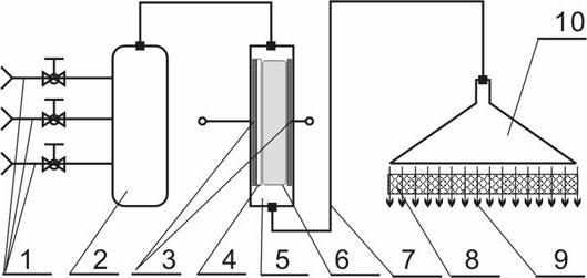
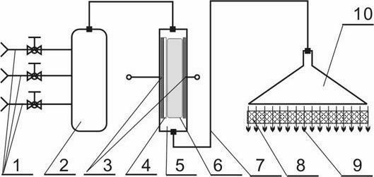
[0045] (2) The structure of the plasma reaction area 6 adopts a single-layer dielectric structure of "electrode plate 3-electrolyte plate 4-plasma reaction area-electrode plate 3", and the electrolyte plate 4 adopts a quartz glass plate with an area slightly larger than the electrode plate 3 and a thickness of 2mm. Material relative permittivity ε=3.7;

[0046] (3) The mixed gas component is air, the temperature is 25°C, and the pressure is 1.0atm. The mixed gas is passed into the plasma reaction zone 6 to generate activated reaction gas 9. After being evenly distributed by the gas balance distributor, it is passed into the carbon felt material from the vertical direction 8. Response tim...

Embodiment 2

[0052] (1) After soaking the viscose-based graphite felt material with a thickness of 10mm in distilled water, the ultrasonic vibration time is 60 minutes, after taking it out, put it in a vacuum oven and dry it at 150°C for 2 hours, and store it in a dry box for later use;

[0053] (2) The structure of the plasma reaction area 6 adopts a double-layer dielectric structure of "electrode plate 3-electrolyte plate 4-plasma reaction area 6-electrolyte plate 4-electrode plate 3", and the area of ​​the electrolyte plate 4 is slightly larger than that of the electrode plate 3, with a thickness of 3mm Al2O3 plate, material relative permittivity ε=6.5;

[0054] (3) The composition of the mixed gas is air, the temperature is 50°C, and the pressure is 4.0 atm. Within 30 minutes, the mixed gas is passed into the plasma reaction zone 6 to generate activated reaction gas 9. Pass into the graphite felt material;

[0055] Finally, an electrode-activated graphite felt material is obtained. ...

Embodiment 3

[0058] (1) After soaking the cellulose-based graphite-carbon mixed felt material with a thickness of 1 mm in distilled water, the ultrasonic vibration time is 20 minutes, after taking it out, put it in a vacuum oven and dry it at 80 ° C for 4 hours, and store it in a dry place. spare in the box;

[0059] (2) The structure of the plasma reaction zone 6 adopts a single-layer dielectric structure of "electrode plate 3-electrolyte plate 4-plasma reaction zone 6-electrode plate 3", and the electrolyte plate 4 adopts quartz glass with an area slightly larger than that of the electrode plate 3 and a thickness of 1mm plate;

[0060] (3) The composition of the mixed gas is oxygen, gaseous titanium tetrachloride and atomized manganese acetate solution, the temperature is 100°C, and the pressure is 0.2atm. Within 2 hours, 60% (volume) oxygen, 20% (volume) tetrachloride The mixed gas of titanium chloride gas and 20% (volume) chloroiridic acid water mist is passed into the plasma reactio...


PUM

PropertyMeasurementUnit
Thicknessaaaaaaaaaa
Thicknessaaaaaaaaaa
Thicknessaaaaaaaaaa

Abstract

The invention provides a method for modifying a carbon porous material, characterized in that by applying a high pressure pulse voltage on two opposite plate electrodes and inserting an electrolyte plate which has a high dielectric constant and a compact structure and has an area that is slightly larger than the size of the plate electrodes between the two opposite plate electrodes, a uniform discharge plasma reaction zone is formed between the plate electrodes; mixed gasses containing oxygen are uniformly mixed at normal temperatures and pressures, the mixed gasses are subject to ionization activation by the plasma reaction zone to generate a plurality of oxygen-containing plasma gasses, after gas distribution is carried out, the gasses vertically flow through a pre-cleaned carbon porous material in the thickness direction to react to obtain the activated carbon porous material. The method has the advantages of environmental protection, low cost, mild treatment conditions, easy control of function group quantity, and outstanding improvement of the activity of the electrode material, and the method can realize gradient treatment, can reduce the area resistance of the contacting surface of the porous material and the bipolar plate, so as to increase the battery efficiency. The method uses devices, thus the method is easy for industrialized operation.

Description

technical field [0001] The invention relates to the field of battery manufacturing and chemical energy storage, in particular to a method of improving the activity of a vanadium battery electrode material by using a plasma treatment method. Background technique [0002] Electric energy is the most important and indispensable secondary energy in the information society, and it is the guarantee for sustainable economic development and social progress. Renewable energy sources such as wind, solar and tidal power are considered to be effective sources of future electricity and are gaining increasing attention worldwide. In order to ensure the stable power supply of the renewable energy power generation system, it should be regulated by means of electric storage and energy storage. All-vanadium redox flow battery (referred to as vanadium battery) is a new type of green energy storage battery. It has many advantages such as high current charge and discharge resistance, easy capac...

Claims


Application Information

Patent Timeline
IPC IPC(8): H01M4/88
CPCY02E60/50
Inventor 禹争光邱述林
Owner DONGFANG TURBINE CO LTD
Learn More