Manufacturing method of high-efficiency nano antenna solar battery

A technology for solar cells and nano-antennas, which is applied in circuits, electrical components, and final product manufacturing, etc., can solve the problems of time-consuming and energy-consuming, multi-silicon semiconductor layers, and inability to save silicon materials, and achieve the effect of simplifying the process and saving costs.

Inactive Publication Date: 2012-10-03
UNIV OF SHANGHAI FOR SCI & TECH
View PDF3 Cites 14 Cited by
  • Summary
  • Abstract
  • Description
  • Claims
  • Application Information

AI Technical Summary

Problems solved by technology

[0004] Nano-antenna solar cells adopt a top-down preparation process. The traditional preparation process requires complex energy-consuming processes such as magnetron sputtering...

Method used


Image

  • Manufacturing method of high-efficiency nano antenna solar battery
  • Manufacturing method of high-efficiency nano antenna solar battery

Examples


Embodiment 1

[0028] A) Metal substrate modification

[0029] Such as figure 1 As shown, a copper foil 1 with a size of 50x50mm is selected as the substrate. According to the mass volume ratio of nano-silicon (g): anhydrous ethanol (ml) ratio of 1:200, prepare a nano-silicon cloud solution with a diameter of 70nm, and ultrasonically disperse it evenly for 1 hour. Select high-frequency, 25°C conditions for ultrasound. The treated nano-silicon solution is spin-coated on the copper foil 1 . During spin coating, use a low speed of 200r / min for 10 seconds, and a high speed of 1500r / min for 10 seconds.

[0030] B) Fabrication of battery device sheet

[0031] The graphene-silicon mixture 102 and carbon nanotubes 2 are grown by chemical vapor deposition at a temperature of 800° C. and a standard pressure of 40 Pa, using ethanol as a carbon source. During the whole process, hydrogen gas is used as reducing agent with a flow rate of 50 sccm. Growth was performed using a vacuum tube furnace.

...

Embodiment 2

[0039] A) Metal substrate modification

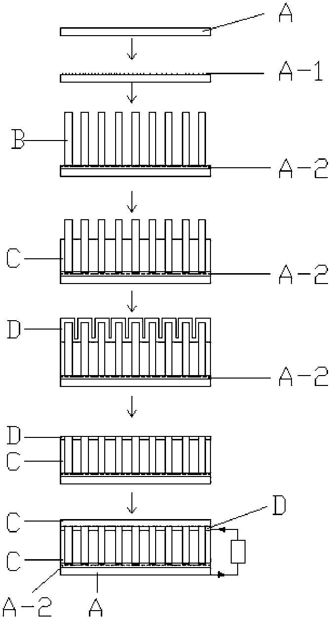
[0040] According to the mass volume ratio of nano-silicon (g): anhydrous ethanol (ml) ratio of 1:200, prepare a nano-silicon cloud solution with a diameter of 30nm, and ultrasonically disperse it evenly for 1 hour. Nickel foil A is selected as the metal substrate, and nano-silica powder A-1 particles with a particle size of 30nm are modified on the surface of the nickel foil by dipping-pulling method.

[0041] B) Fabrication of battery device sheet

[0042] Using acetylene as the carbon source gas, graphene-silicon mixture A-2 and carbon nanotubes B were grown by plasma-enhanced chemical vapor deposition at 850°C and 100 Pa standard pressure. During the whole process, hydrogen gas is used as reducing agent with a flow rate of 50 sccm.

[0043] C) Passivation layer fabrication

[0044] A silicon dioxide passivation layer C is formed between the generated carbon nanotubes B by magnetron sputtering.

[0045] D) Window layer production ...

Embodiment 3

[0050] The concrete steps of this embodiment are identical with embodiment 1, and difference is:

[0051] A) Choose iron foil as the metal substrate. Acetone was chosen as the organic solvent. According to the mass-volume ratio of nano-silicon (g): acetone (ml) ratio of 1:200, configure a nano-silicon turbid solution with a diameter of 50nm.

[0052] B) When the cell device is fabricated, the conditions are: methane as the carbon source, at a temperature of 950°C, and a standard pressure of 60Pa

[0053] C) The finally obtained solar cell uses the iron foil substrate as the back electrode, and the upper ZnO transparent conductive film as the front electrode.


PUM

PropertyMeasurementUnit
Particle sizeaaaaaaaaaa

Abstract

The invention relates to a manufacturing method of a high-efficiency nano antenna solar battery. The manufacturing method comprises the following steps of: preparing turbid liquid from an ethanol or acetone organic solvent and nano silicon powder according to a massic volume ratio of nano silicon (g) to the organic solvent (ml) of 1:200, and spin-coating the turbid liquid onto a metal substrate for carrying out substrate modification by a spin coating method; and growing a silicon-graphite-carbon nano tube composite structure on the substrate in one step under the conditions of temperature of 800-1000 DEG C and standard pressure intensity of 40-100Pa and forming a solar battery device sheet; generating a silicon rubber or silicon carbide or alumina passivation layer among carbon nano tubes by adopting a spin coating process or sputtering or evaporating; and depositing a transparent conductive film on the upper layer of the device sheet by adopting methods, such as an electron beam evaporation method and a magnetron sputtering method, and finally obtaining the high-efficiency nano antenna solar battery by taking the metal substrate and the transparent conductive film as electrodes. The manufacturing method disclosed by the invention can be used for directly generating a nano solar battery main structure by adopting a one-step method, is simple and highly-efficient, saves raw materials and cost and is suitable for large-scale production.

Description

technical field [0001] The invention relates to a manufacturing method of a high-efficiency nano-antenna solar cell, which belongs to the fields of microelectronics, solid-state electronics, and nanometer science and technology. Background technique [0002] In the field of solar cells today, according to the different materials used, solar cells are mainly divided into: silicon solar cells, multiple semiconductor compound thin film solar cells, dye-sensitized solar cells, organic polymer solar cells, plastic solar cells, etc., among which silicon solar cells It is currently the most mature and occupies a dominant position in the application. Due to the high cost of silicon material growth, high energy consumption and heavy pollution, and its efficiency is limited, it is difficult to further improve it. Therefore, the development of new structural solar cells has become a research hotspot in the field of solar cells. [0003] In recent years, with the increasing applicatio...

Claims


Application Information

Patent Timeline
IPC IPC(8): H01L31/18
CPCY02P70/50
Inventor 门传玲曹军邓闯朱德明曹敏张华
Owner UNIV OF SHANGHAI FOR SCI & TECH
Why Eureka
Try Eureka