Coke dry quenching method for coal coking device

A technology of dry quenching and coke quenching tower, which is applied in coke oven, coke cooling, petroleum industry, etc., and can solve the problems of low energy utilization rate, poor heat transfer effect and large investment

Inactive Publication Date: 2012-10-17
何巨堂
View PDF9 Cites 13 Cited by
  • Summary
  • Abstract
  • Description
  • Claims
  • Application Information

AI Technical Summary

Problems solved by technology

[0005] ②Water quenching causes anhydrous hot charcoal to become water-containing cold charcoal, with a water content of 7.5 tons/hour, accounting for about 10% of the semi-coke product volume; in order to reduce moisture, correspondingly increase the drying and dehydration steps, usually using indirect heating in a drying kiln or Gas combustion flue gas is directly heated and dried, resulting in low heat transfer efficiency, high energy consumption, and large system investment;
[0007] ④ The drying process of coke containing water causes water loss and gas consumption
[0011] ③Low energy utilization rate in the drying process: during direct drying, due to the small temperature difference, low operating pressure, and low density of direct heat transfer gas phase medium, the heat transfer effect is poor and the equipment is huge; during indirect drying, the operating pressure is low and direct The density of the heat transfer gas phas

Method used


Image

  • Coke dry quenching method for coal coking device
  • Coke dry quenching method for coal coking device
  • Coke dry quenching method for coal coking device

Examples


Embodiment 1

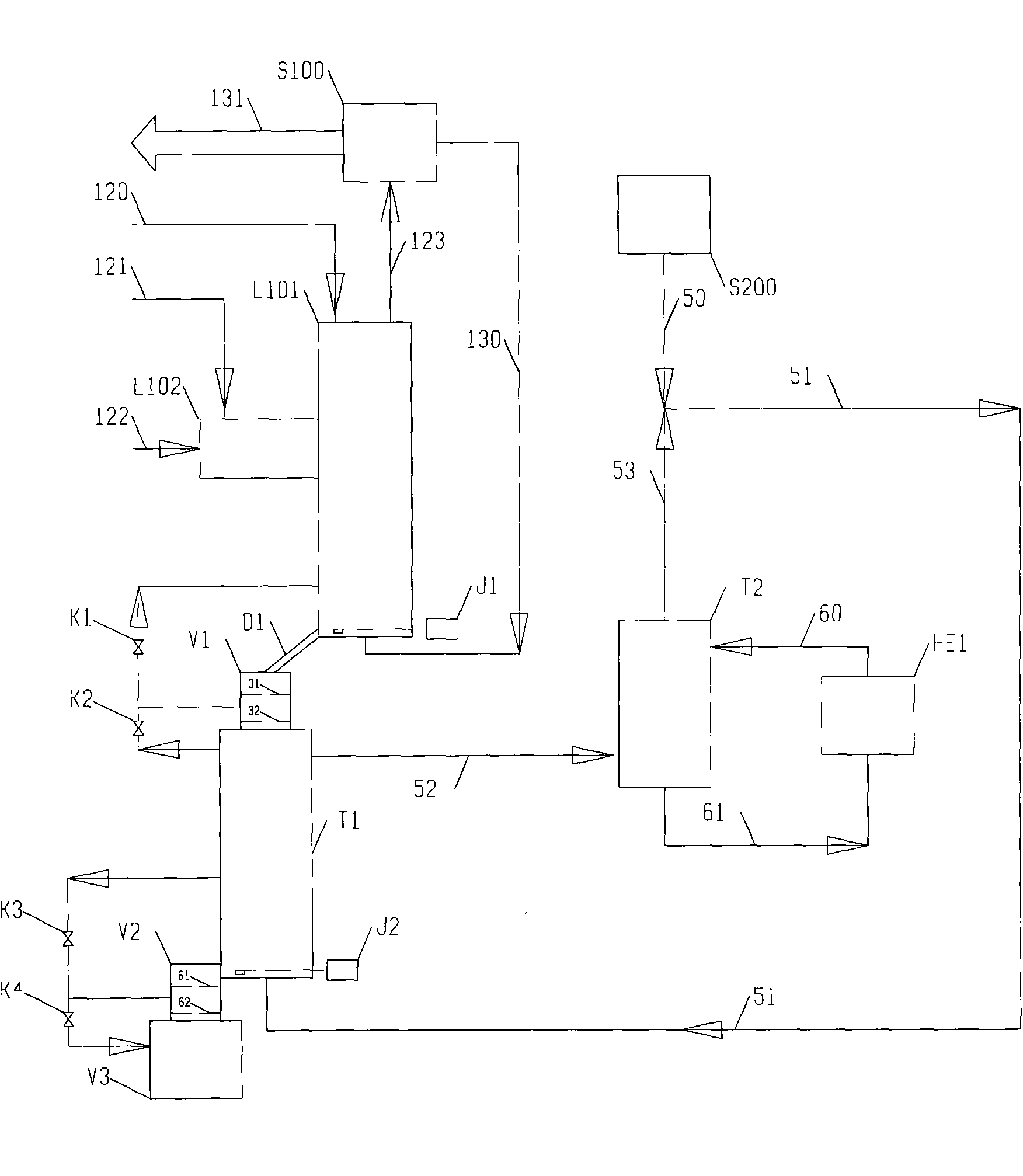
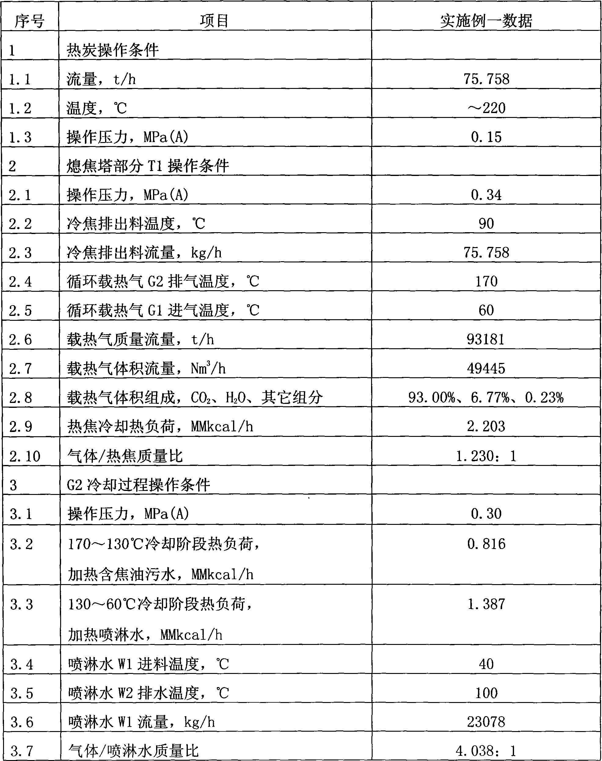
[0161] According to the present invention, the semi-coke device adopts dry coke quenching, and its flow process is as attached figure 1 As shown, the operating conditions of each step are shown in Table 4. The heat carrier gas is furnace flue gas or nitrogen or CO 2 Gas, this embodiment uses CO 2 Gas, which is CO-enriched from the pressure swing separation part of the carbonization process product gas 2 Gases (these gases are the combustion products of carbon and oxygen in the fuel gas of the coking process).

[0162] In the PSA hydrogen production part of the gas, activated carbon is used in the PSA1 part to absorb the tar component in the gas under the pressure of 0.5MPa to obtain the detarred gas; Adsorption of CO in detarred gas 2 ; In the PSA3 part, activated carbon and molecular sieve adsorbents are used to complete CO removal under the pressure of 1.0MPa 2 Separation of hydrogen components and non-hydrogen components in coal gas to obtain high-purity hydrogen; in t...


PUM


Abstract

The invention discloses a coke dry quenching method for a coal coking device. The coke dry quenching method is suitable for a semi-coking device. Usually, multiple coking chambers share a coke quenching system. The coke dry quenching method comprises that 1, hot coke from the bottom of a coke cooling section of a coking chamber is pushed to a hot coke transferring warehouse V1 by a coke pusher J1; 2, the hot coke is regularly discharged into the hot coke transferring warehouse V1 by a V1 charging valve and then the V1 charging valve is closed; and after the hot coke transferring warehouse V1 is pressurized by gas from a coke quenching tower T1, the hot coke is regularly discharged into the coke quenching tower T1; 3, the coke quenching tower T1 is operated under pressurized conditions and the hot coke moves from bottom to top under the action of gravity and contacts with inert gas such as CO2 flowing from bottom to top so that a temperature of the hot coke is reduced; and the cold coke is pushed into a cold coke transferring warehouse V2 by a coke pusher J2; 4, the cold coke is regularly discharged into the cold coke transferring warehouse V2 by a V2 charging valve and then the V2 charging valve is closed; and after the cold coke transferring warehouse V2 is deflated so that a cold storage chamber V3 is depressurized, the cold coke is regularly discharged into the cold storage chamber V3 or is transmitted into the cold storage chamber V3 by a belt; and 5, hot heat-carrying gas G2 departing from the coke quenching tower T1 enters into a spray tower T2 and then carries out counter-current contact with recycled cold spray water W1 so that the hot heat-carrying gas G2 is cooled by heat transmission; and the cooled gas as G1 is fed back to the coke quenching tower T1 for recycle.

Description

technical field [0001] The invention relates to a coke dry quenching method for a coal coke production device, in particular to a coke dry quenching method for a coal semi coke (blue coke) device. Background technique [0002] At present, an imperfection in the coal-to-semi-coke industry coexists: Regardless of the internal heating or external heating technology, semi-coke quenching adopts water quenching to quickly extract heat, and then water quenching goes through the drying and dehydration process to control The final water content of the semi-coke product. [0003] As we all know, the Anshan Thermal Energy Research Institute of China Iron and Steel Group began to continuously research and develop in the early 1980s the technology of "using non-caking coal or weakly caking coal lump coal as raw material to make semi-coke for ferroalloy in vertical carbonization furnace" (hereinafter Sinosteel Coal Conversion Technology BT for short), adopts suitable coal sources (such a...

Claims


Application Information

Patent Timeline
IPC IPC(8): C10B39/02
Inventor 何巨堂
Owner 何巨堂
Why Eureka
Try Eureka