Wet method used for preparing sulfuric acid from exhaust gas containing hydrogen sulfide

A technology for hydrogen sulfide and sulfuric acid production, which is applied in chemical instruments and methods, sulfur compounds, inorganic chemistry, etc., can solve the problems of high pressure level of waste heat recovery equipment, difficult manufacturing operations, and easy to be exposed to dew point corrosion, and achieves by-product steam. The effect of improving heat recovery efficiency and avoiding dew point corrosion of heat exchange tubes

Inactive Publication Date: 2014-03-12
CHINA PETROLEUM & CHEM CORP +1
View PDF8 Cites 27 Cited by
  • Summary
  • Abstract
  • Description
  • Claims
  • Application Information

AI Technical Summary

Problems solved by technology

[0010] The purpose of the present invention is to solve the existing hydrogen sulfide-containing waste gas wet-process acid production tail gas sulfur dioxide, nitrogen oxides and acid mist are easy to exceed the standard, and waste heat recovery equipment is faced with high pressure levels, difficult manufacturing operations, and easy dew point corrosion. A method that uses dilute sulfuric acid to pre-deammoniate, reduce / oxidize and incinerate to control the amount of nitrogen oxides generated, heat pipe heat exchange equipment to reduce the possibility of equipment dew point corrosion, and at the same time, adopt tail gas desulfurization and denitrification methods to further remove sulfur dioxide and acid mist in the tail gas NOx method

Method used


Image

  • Wet method used for preparing sulfuric acid from exhaust gas containing hydrogen sulfide

Examples


Embodiment Construction

[0034] The present invention will be further described below in conjunction with the accompanying drawings and specific embodiments.

[0035] The embodiment of the present invention specifically adopts following technological process:

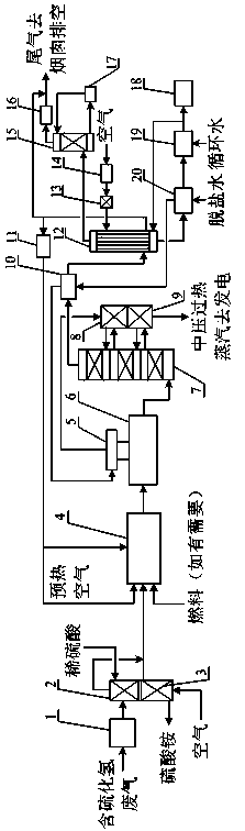
[0036] figure 1 The waste gas containing hydrogen sulfide in the waste gas is stabilized to a certain pressure by the equipment 1 and then sent to the equipment 2, and is in countercurrent contact with the dilute sulfuric acid sprayed on the top of the tower to wash and remove the ammonia in the waste gas containing hydrogen sulfide. The washing liquid flows into the equipment 3, and the hydrogen sulfide gas in the washing liquid is taken out by introducing air. The stripping gas is mixed into the gas at the outlet of equipment 2, and then sent to equipment 4 for incineration. The ammonium sulfate solution from equipment 3 is sent to evaporation and concentration to produce solid products. The combustion-supporting air sent by the equipment ...


PUM

PropertyMeasurementUnit
quality scoreaaaaaaaaaa

Abstract

The invention discloses a wet method used for preparing sulfuric acid from exhaust gas containing hydrogen sulfide, and belongs to the technical field of waste gas treatment in environmental protection industry and chemical production. The wet method comprises following steps: removal of nitrogen compounds of the exhaust gas containing hydrogen sulfide is realized using dilute sulphuric acid with a mass fraction of 30 to 50%; the treated exhaust gas containing hydrogen sulfide is delivered into an incinerator, preheated air is added so as to maintain a combustion temperature of 700 to 1000 DEG C and a reducing/oxidizing atmosphere, so that sufficient burning of hydrogen sulfide and other combustible components is realized, and generation amount of nitrogen oxide is reduced; high temperature gas at an incinerator outlet is delivered into a medium pressure waste heat boiler so as to recycle heat energy and byproduct saturated vapour; flue gas containing sulfur dioxide at a waste heat boiler outlet is delivered directly into a converter, and flue gas containing sulfur trioxide and vapour is obtained via primary conversion; reaction heat in the converter is removed in time using heat-exchange equipment; flue gas at a converter outlet is delivered into at least primary-stage condenser tube pass, and an appropriate amount of air is delivered into condenser shell pass to be used as a cooling medium; heat energy of high temperature concentrated sulfuric acid flows out from the bottom of the condenser is recycled via a desalting water preheater and an acid cooler; and exhaust gas at a condenser outlet is delivered into a desulfurization tower so as to remove sulfur dioxide and nitrogen oxides.

Description

technical field [0001] The invention belongs to the technical field of waste gas treatment and chemical production in environmental protection, and in particular relates to a wet method for producing sulfuric acid from waste gas containing hydrogen sulfide. technical background [0002] Waste gas containing hydrogen sulfide is generally produced in the processes of petroleum refining, natural gas purification, coking, coal gasification and viscose fiber production. Hydrogen sulfide-containing waste gas sometimes also contains carbonyl sulfide, carbon disulfide, ammonia and other components. Because hydrogen sulfide is highly toxic and flammable, the gas cannot be released directly into the atmosphere and must be disposed of. Conventional methods for treating waste gas containing hydrogen sulfide include the recovery of sulfur by the Claus method, or the production of sulfuric acid by wet or dry processes. The Claus method has a long process flow and a large investment in e...

Claims


Application Information

Patent Timeline
Patent Type & Authority Applications(China)
IPC IPC(8): C01B17/74
CPCY02P20/129
Inventor 纪罗军魏兰明素荣张成昆吴英来
Owner CHINA PETROLEUM & CHEM CORP
Why Eureka
Try Eureka