Carbon fiber-based coated sand material for selective laser sintering and preparation method thereof

A laser sintering and carbon fiber technology, applied in manufacturing tools, casting molding equipment, metal processing equipment, etc., can solve the problems of short laser beam irradiation time, large sand mold gas generation, poor air permeability and collapsibility, etc., to achieve rapid response manufacturing capabilities Huge, enhanced effect, improved thermal stability

Inactive Publication Date: 2016-08-17
NANCHANG HANGKONG UNIVERSITY
View PDF4 Cites 2 Cited by
  • Summary
  • Abstract
  • Description
  • Claims
  • Application Information

AI Technical Summary

Problems solved by technology

Due to the poor thermal conductivity of the coated sand and the short irradiation time of the laser beam, the sintered parts of the coated sand generally have defects such as low initial strength of sintering and poor surface quality, and the content of the binder is high, resulting in the occurrence of sand molds (cores). Large air volume, poor air permeability and collapsibility, it is difficult to meet the production requirements of complex castings with high quality and high performance

Method used


Image

  • Carbon fiber-based coated sand material for selective laser sintering and preparation method thereof

Examples


Embodiment 1

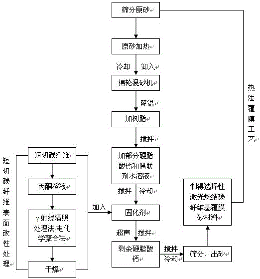
[0030] A carbon fiber-based coated sand material for selective laser sintering is carried out in the following steps:

[0031] Step 1: Use γ-ray irradiation to modify the surface of chopped carbon fibers. First, put the chopped carbon fibers with a diameter of 7 μm and a length of 2.5 mm into an acetone solution, wash them for 48 hours, and then dry them. In the irradiated bottle of tetraethylene glycol acetone solution with active functional group concentration of 2 mol / L, one end of the two vent holes of the irradiated bottle was continuously ventilated with nitrogen for 2 min, and sealed after the oxygen in the bottle was removed. Put it in a Coγ-ray irradiation source, and carry out co-irradiation grafting modification according to the irradiation dose of 200kGy. After the chopped carbon fibers were irradiated, they were cleaned with acetone and dried in a vacuum oven at 50 °C for 12 h for later use.

[0032] Step 2: Using the thermal coating process, sieve the spherical ...

Embodiment 2

[0037] A carbon fiber-based coated sand material for selective laser sintering is carried out in the following steps:

[0038] Step 1: Use electrochemical polymerization to modify the surface of chopped carbon fibers. First, put the chopped carbon fibers with a diameter of 7 μm and a length of 1.5 mm into an acetone solution for 48 hours, and then use sulfuric acid as an electrolyte to deionize Water was used as a solvent, and monomers with a mass fraction of 1% were added to form an electrolyte. Then carbon fiber was used as an anode and graphite was used as a cathode. At room temperature, electrolytic polymerization was carried out at a polymerization current of 90 mA for 60 seconds, and then deionized water was used to The surface of the chopped carbon fiber was cleaned to remove residual electrolyte ions and unpolymerized monomers on the surface, and finally it was dried in a vacuum oven at 50 °C for 12 h for later use.

[0039] Step 2: Using the thermal coating process, s...


PUM

PropertyMeasurementUnit
diameteraaaaaaaaaa
lengthaaaaaaaaaa
tensile strengthaaaaaaaaaa

Abstract

The invention discloses a carbon fiber-based coated sand material for selective laser sintering and a preparation method thereof; the components of the carbon fiber-based coated sand material are chopped carbon fiber, raw sand, an organic binder, a curing agent, a lubricant, an even Coupling agent and dispersant; its preparation method is: carry out surface modification treatment on chopped carbon fiber, and then prepare according to the following process: raw sand heating—adding resin—adding part of calcium stearate and the prepared coupling agent aqueous solution—adding Hexatropine curing agent containing chopped fibers—adding the remaining calcium stearate—cooling—sieving and sanding out to obtain the product. The advantages of the present invention are: (1) carbon fiber plays a role of heat conduction, which limits the overall shrinkage of the sintered part to a certain extent, and reduces the warping phenomenon in the molding process; The thermal stability of the coated sand can promote the curing reaction of the phenolic resin in the local part of the sintered layer and the joint between the layers, and obviously improve the green strength of the laser sintered formed part.

Description

technical field [0001] The invention belongs to the field of new materials, and in particular relates to a carbon fiber-based coated sand material for selective laser sintering and a preparation method thereof. Background technique [0002] Selective laser sintering technology (SLS) is a solid freeform fabrication technology (Solid Freeform Fabrication, SFF) that uses laser as a controllable heat source to selectively sinter powder materials. And manufacturing, through layered slice processing of the 3D CAD model of the part, the cross-sectional profile information of each layer is obtained, and then the solid powder material is sintered, so that the layers are bonded to each other and gradually superimposed, so as to quickly obtain the three-dimensional entity. It is not restricted by the complexity of the shape and structure of the parts, does not require any tooling and molds, and has a short manufacturing cycle and low production costs. Coated sand is one of the common...

Claims


Application Information

Patent Timeline
Patent Type & Authority Patents(China)
IPC IPC(8): B22C1/00B22C1/22B22C1/02
CPCB22C1/00B22C1/02B22C1/2233
Inventor 芦刚毛蒲严青松卢百平余欢
Owner NANCHANG HANGKONG UNIVERSITY
Why Eureka
Try Eureka